- 20.11.2024.
- -
DETAIL D1 – Termination of Waterproofing Around Roof Penetration
Fluid temperature within the roof penetration does not exceed 50°C – for ventilation ducts
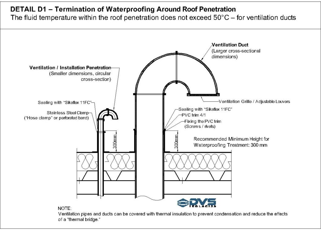
The treatment of roof penetrations with a waterproofing membrane is executed according to recommendations, up to a height of 300 mm above the roof surface.
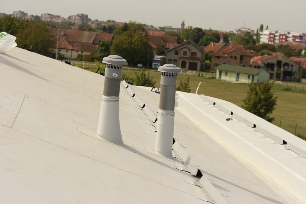
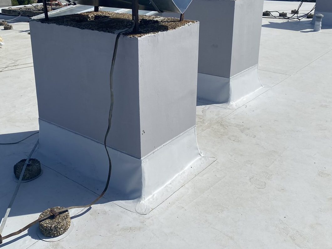
Ventilation ducts may also be covered with thermal insulation, followed by a waterproofing membrane.
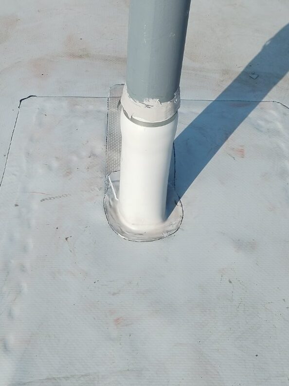
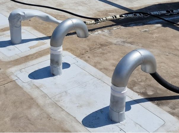
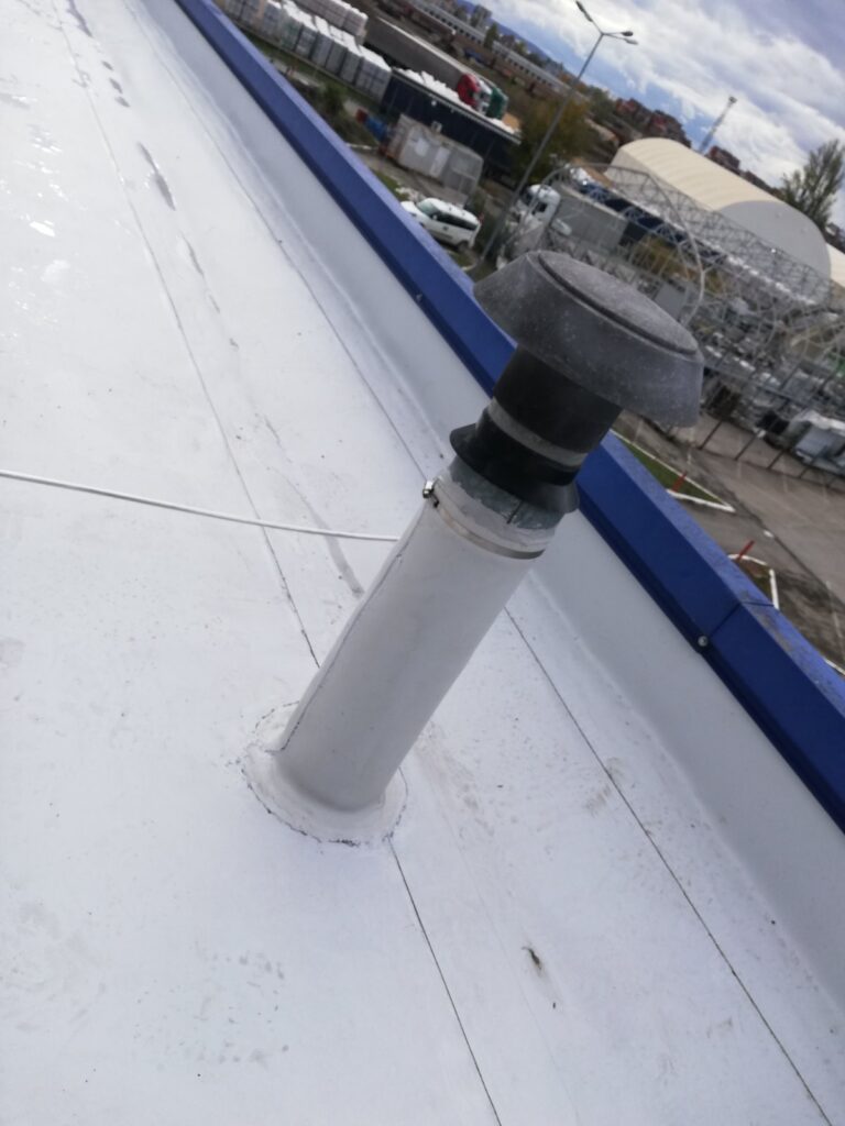
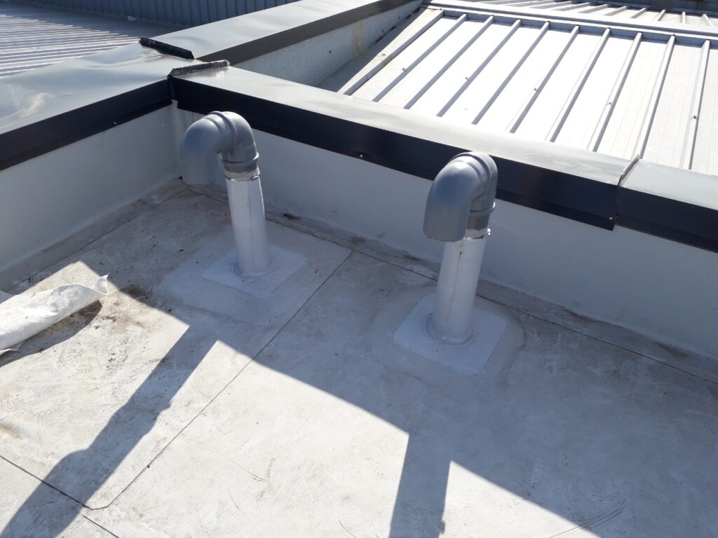
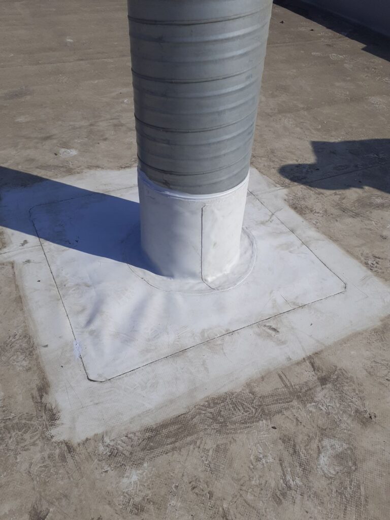
Installation pipes with circular cross-section (hereinafter abbreviated as c.s.) are wrapped with a separating layer of geotextile, after which the waterproofing membrane is applied and welded.
Afterwards, the joint is sealed with polyurethane sealant and secured with a stainless steel clamp (“hose clamp”) or perforated band. Upon tightening, a watertight seal is achieved.
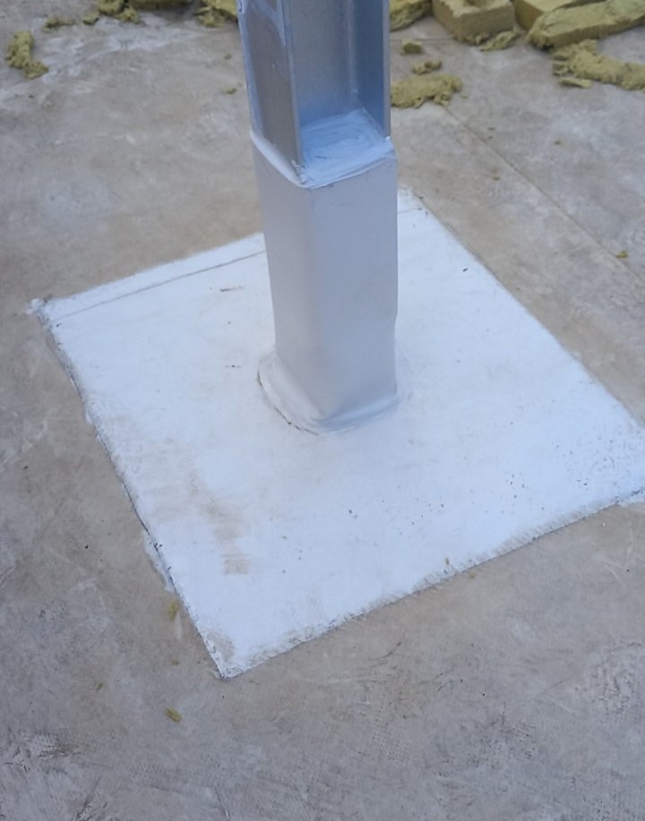
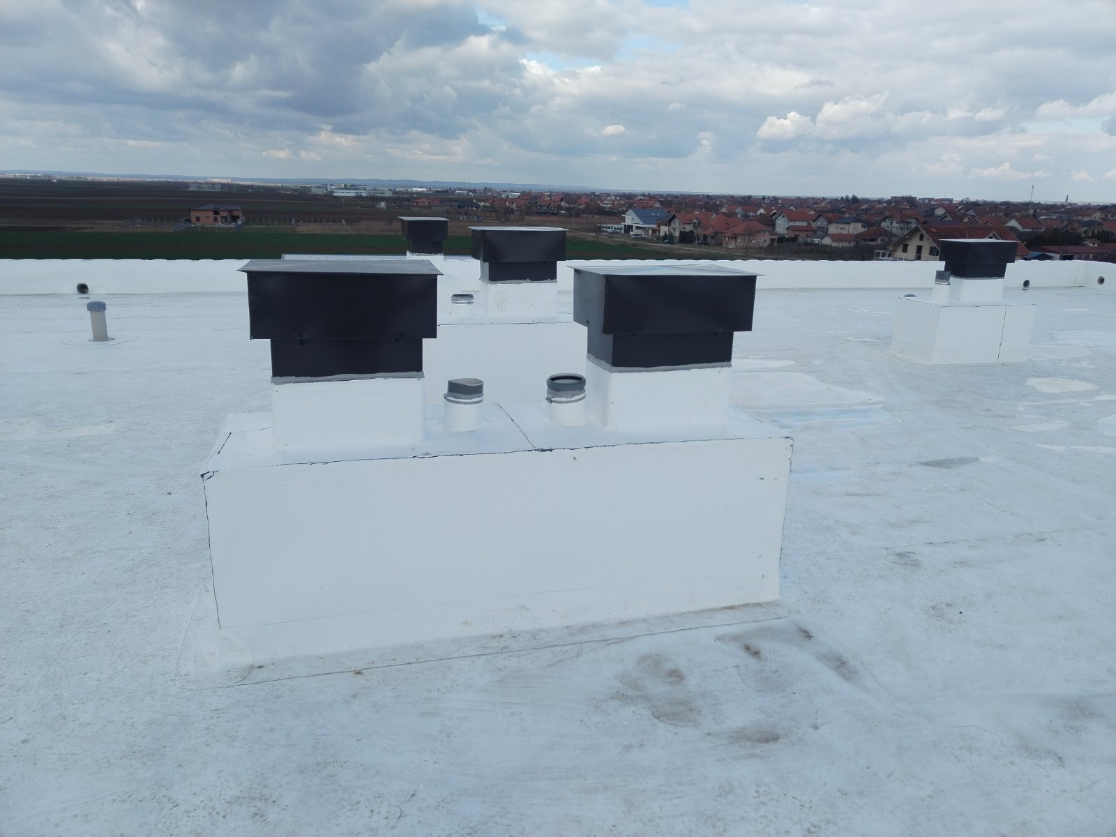
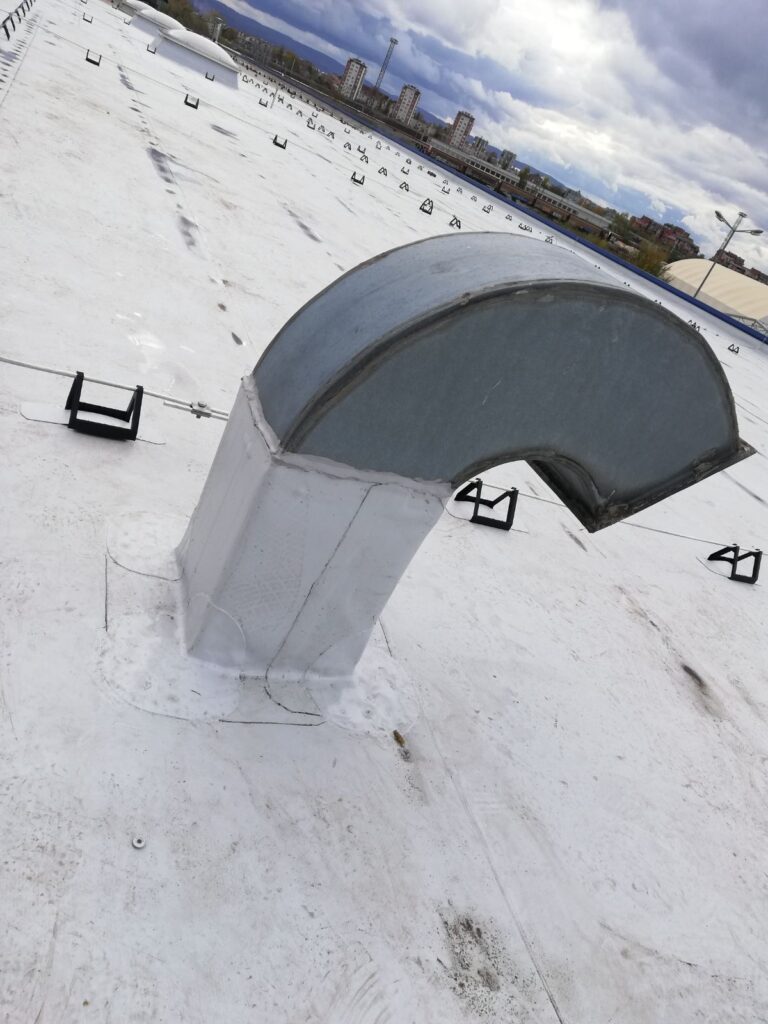
For ventilation ducts with rectangular cross-section, a PVC or FPO termination bar 4/1 is installed around the perimeter and fixed with screws or rivets. The duct is then wrapped with a separating layer of geotextile or mineral wool. The final treatment is done with a waterproofing membrane, hot-air welded to the termination bar and the main roof membrane.
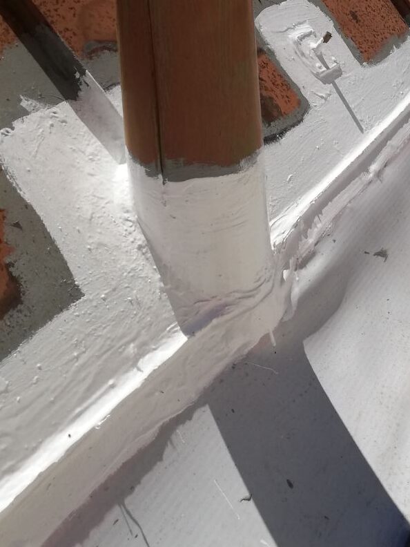
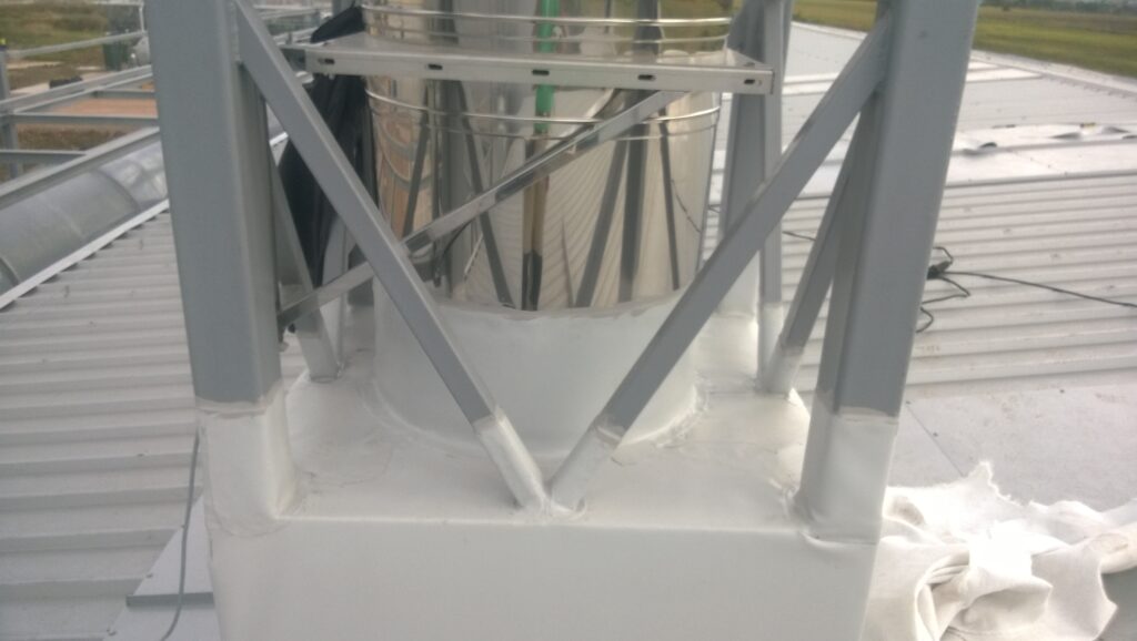
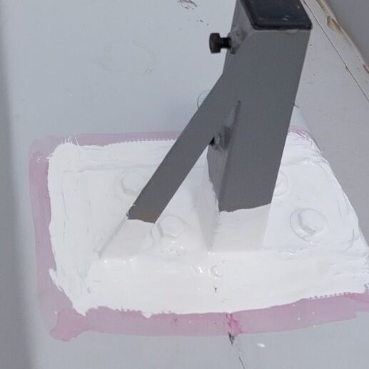
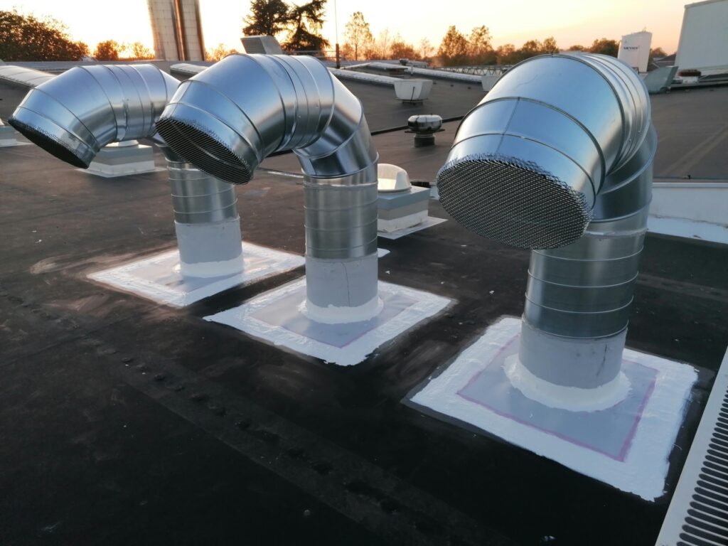
In cases where the geometry of the ventilation ducts is complex or inaccessible for waterproofing membrane application, the penetrations may be waterproofed with a liquid-applied membrane “Sikalastic 641”.
Below are examples of waterproofed ventilation ducts:
DETAIL D2 – Termination of Waterproofing Around Chimneys / Metal Pipes with High Temperature
Fluid temperature within the roof penetration exceeds 50°C – for ventilation ducts / chimneys
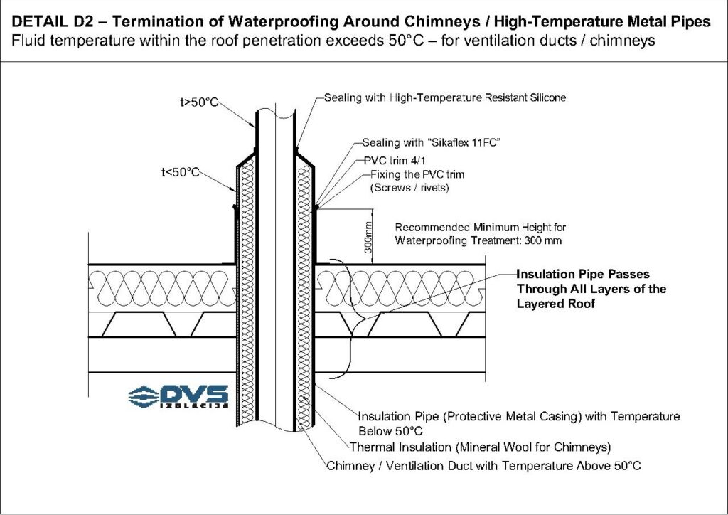
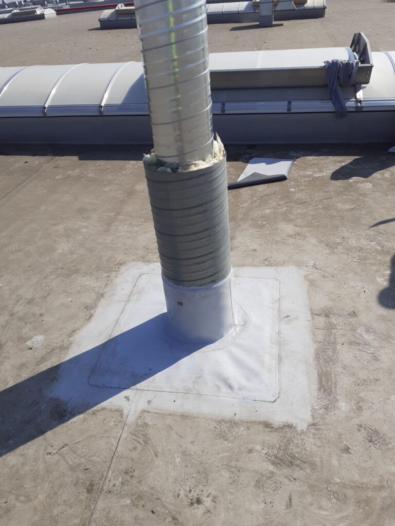
When waterproofing ventilation ducts and chimneys through which air with elevated temperature (above 50°C) flows, the inner pipe must be wrapped with mineral wool for chimneys, followed by a protective metal casing.
The temperature on the outer casing is lower (below 50°C), and as such suitable for waterproofing membrane application.
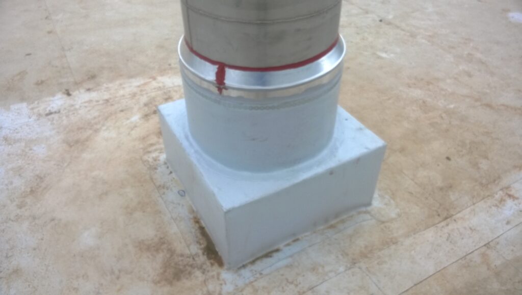
A PVC/FPO termination bar 4/1 is mechanically fixed to the protective casing, and the waterproofing membrane is welded to it. The joint is then sealed with polyurethane sealant.
The assembly of the chimney pipe and protective casing ends with a conical narrowing, sealed with high-temperature resistant refractory silicone.
It is important to note that chimney pipes must be treated with both thermal and waterproofing layers through all roof layers.
If chimneys are made from prefabricated modular elements (stainless steel pipe / thermal insulation / protective metal casing), they are treated identically as described above.
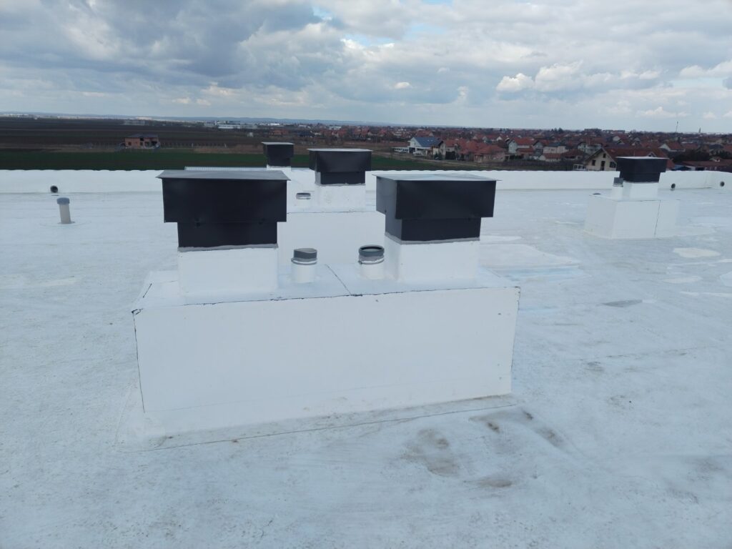
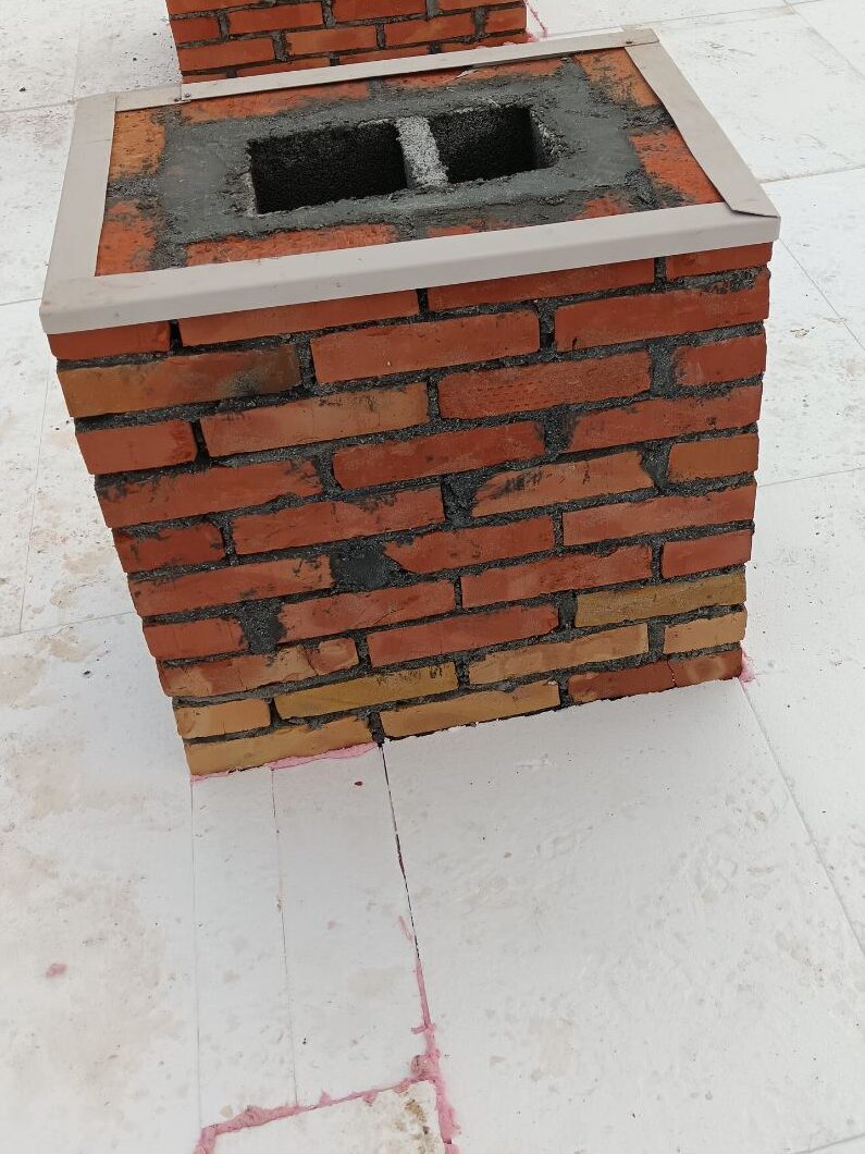
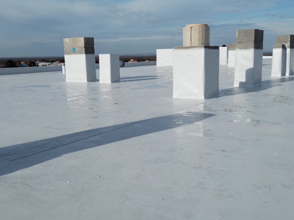
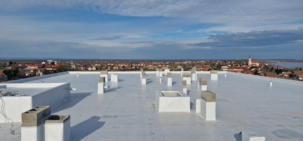
In residential buildings, private houses, or apartment blocks, ventilation ducts and chimneys can be built as masonry shafts. Masonry chimneys are typically constructed from standard modular elements, with ceramic round flue pipes, thermal insulation, and modular blocks. The external surface temperature of such masonry chimneys is below 50°C, allowing waterproofing to be executed per standard details.
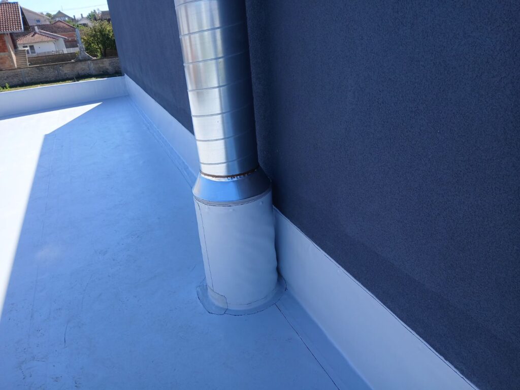
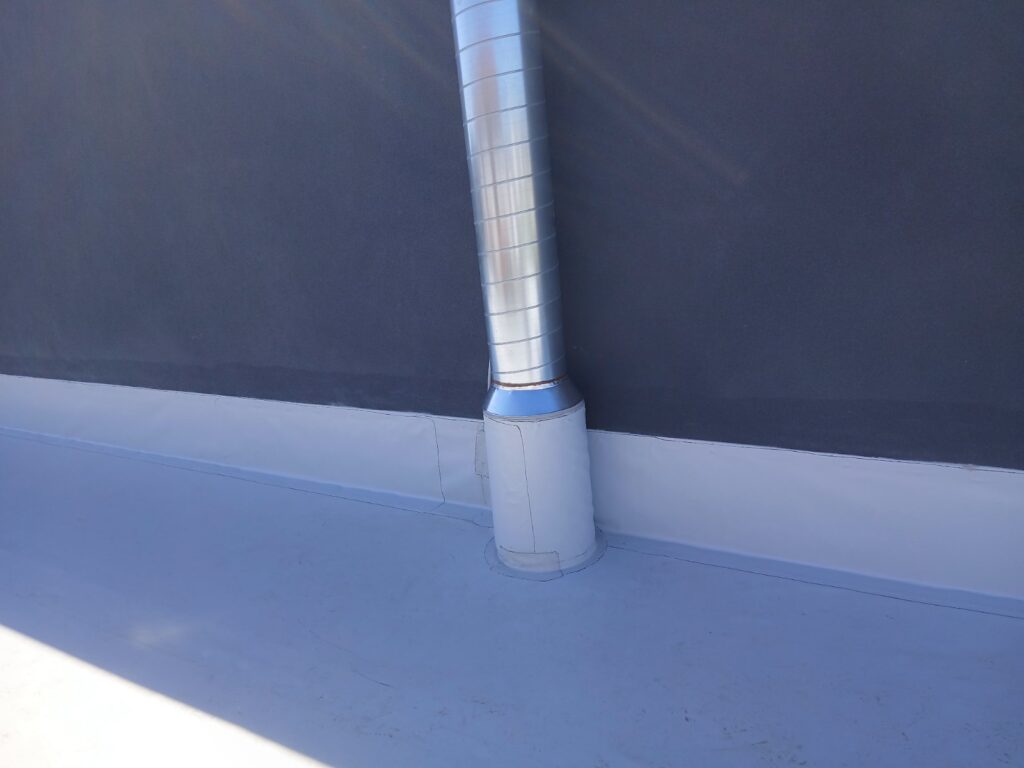
Examples of insulated chimneys / ventilation ducts:
DETAIL D3 – Termination of Waterproofing Around Metal Ducts of HVAC Equipment
(Encapsulation with thermal and waterproofing layers – to prevent condensation within the duct)
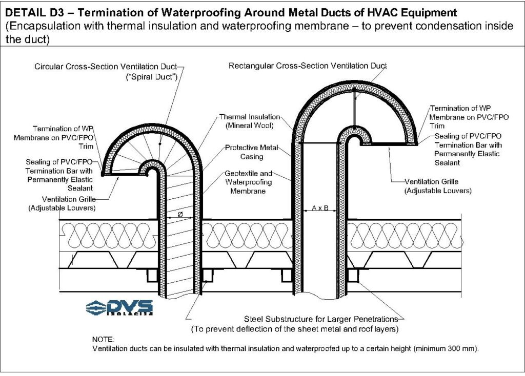
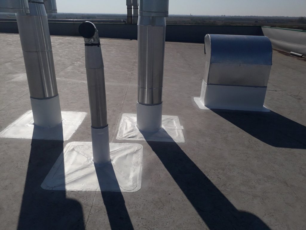
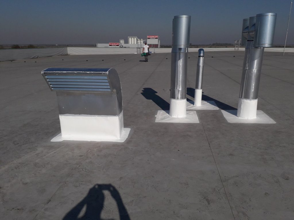
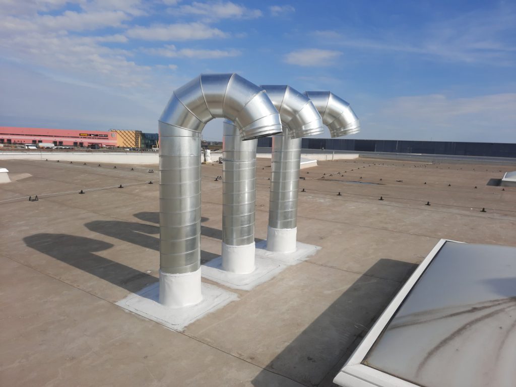
HVAC ventilation ducts are most commonly made of metal ducts with circular or rectangular cross-sections.
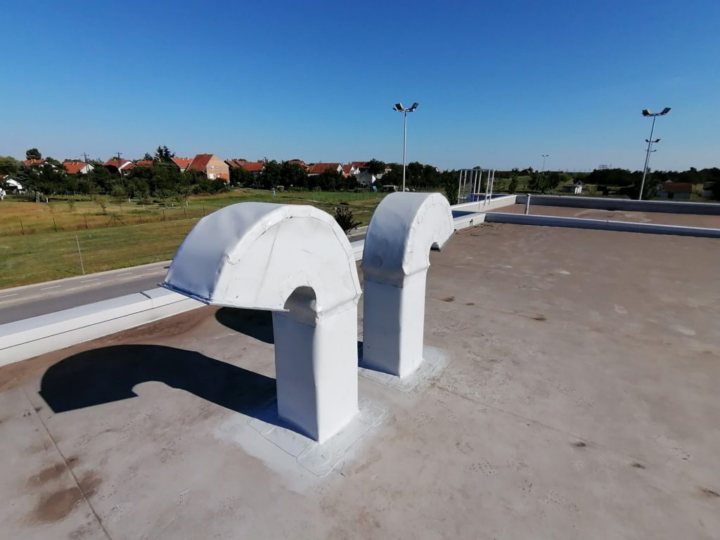
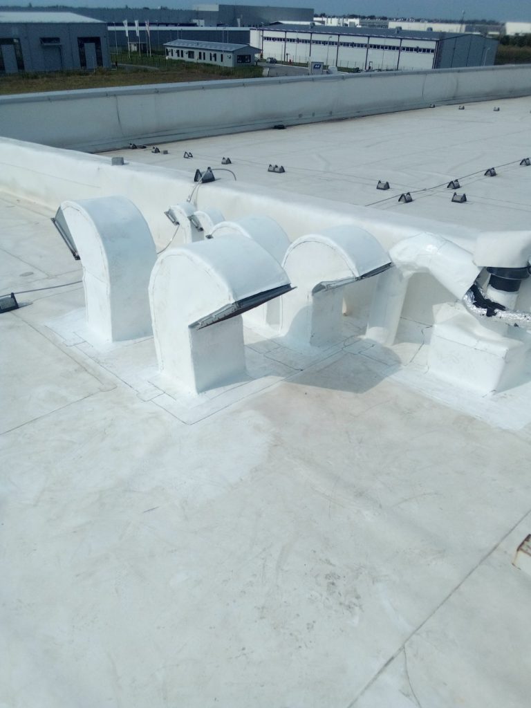
Depending on the temperature difference between the air inside the duct and the ambient environment, ducts can be insulated with thermal insulation, followed by waterproofing membrane application. Thermal insulation prevents condensation inside the duct.
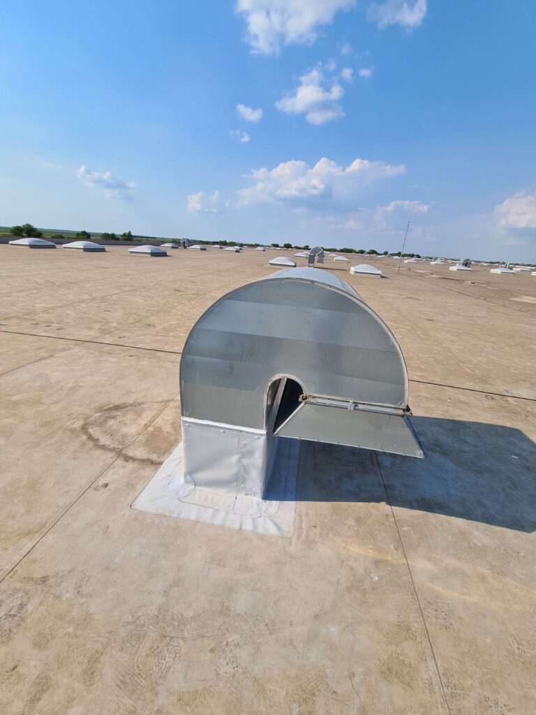
An important note for ventilation duct terminations: louvers/grilles should be installed at an angle less than 45°, to prevent water ingress from precipitation into the duct. In the detail, the angle between the ventilation grille and the roof plane is 0° (or 180°).
Treatment with thermal and waterproofing layers may be executed up to a height of minimum 300 mm, or the entire section above the roof surface.
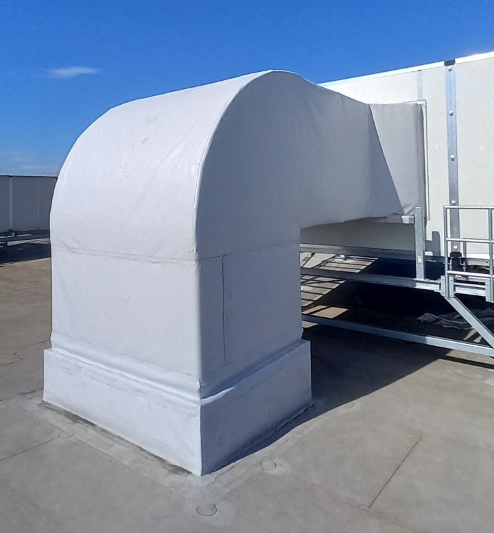
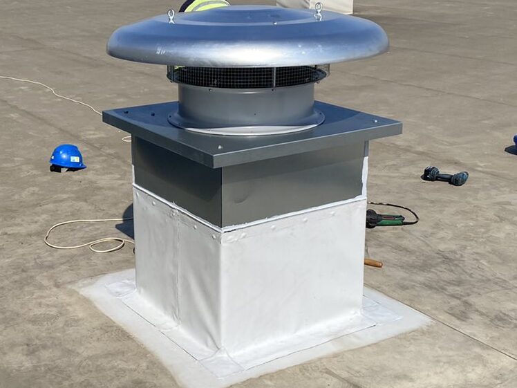
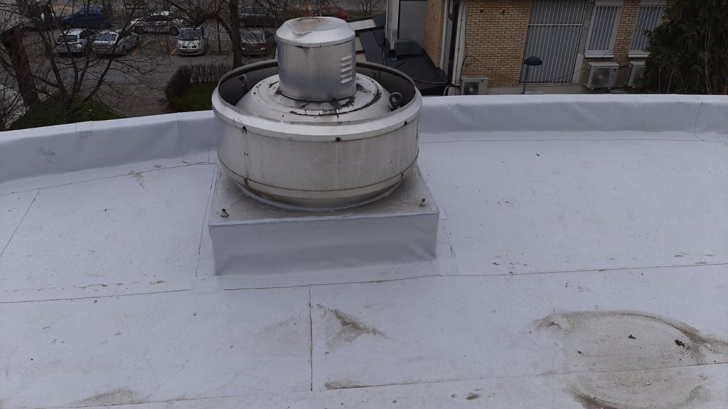
Examples of waterproofed ventilation ducts:
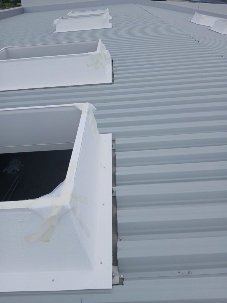
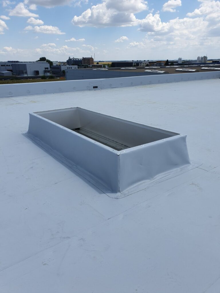
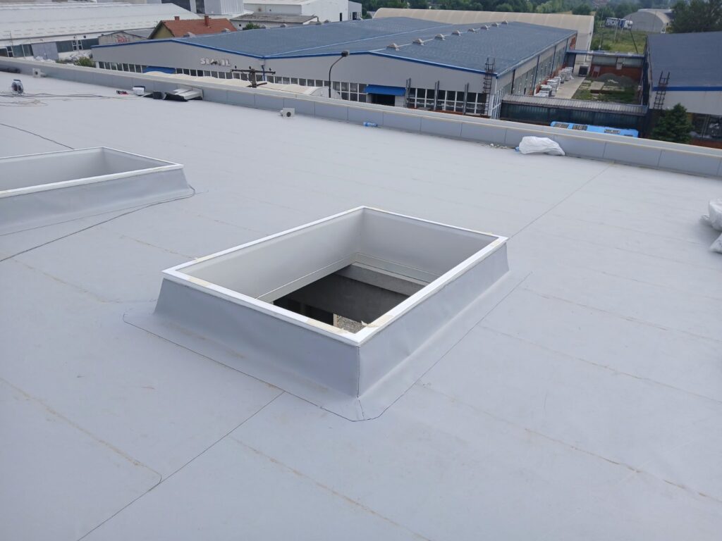
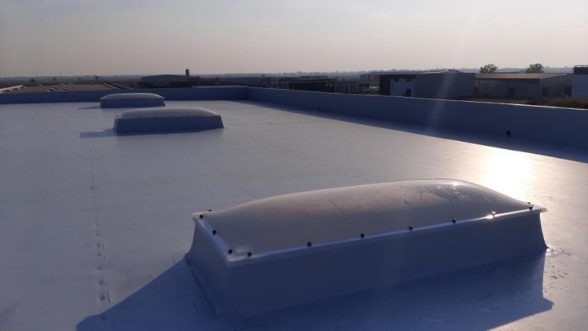
DETAIL D4 – Waterproofing of Roof Domes / Skylights
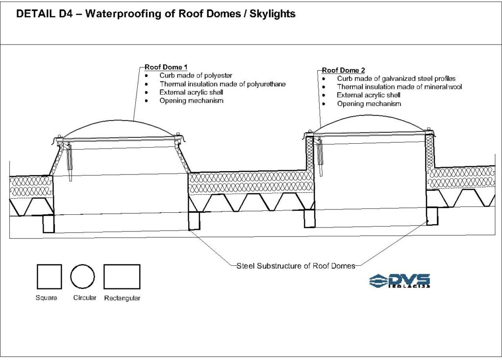
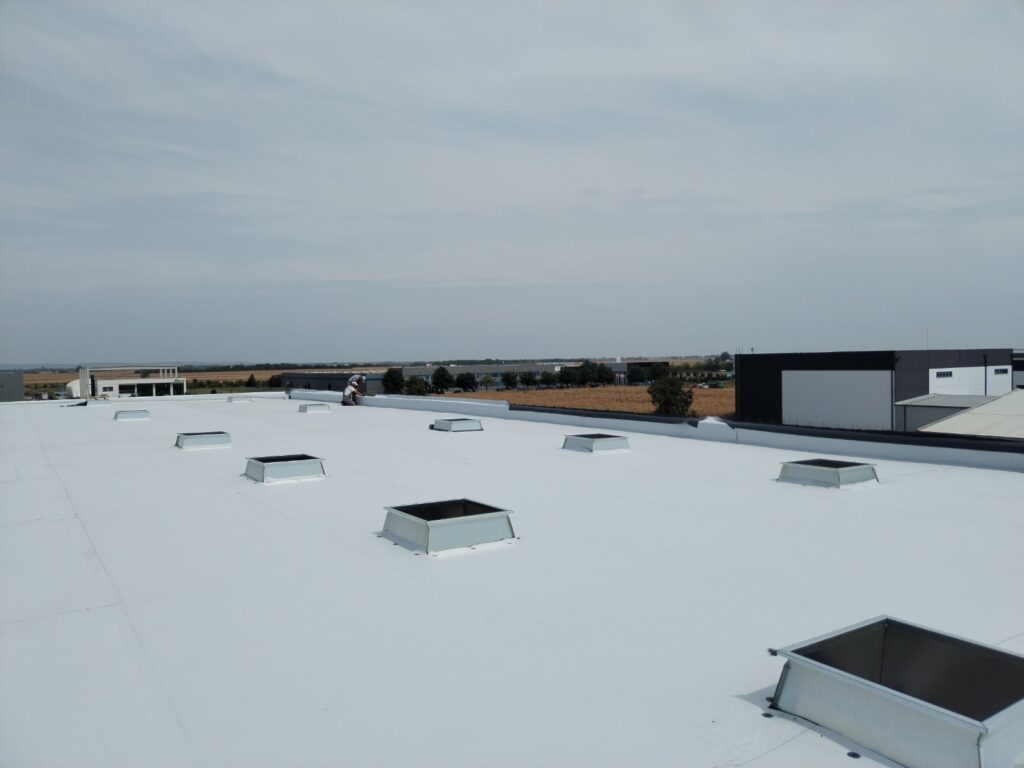
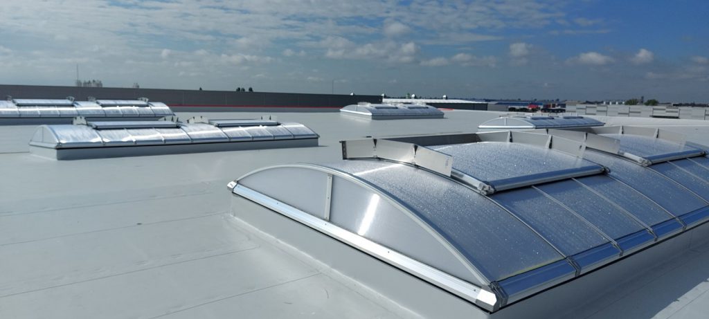
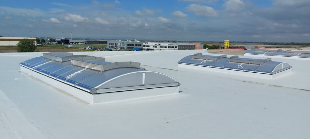
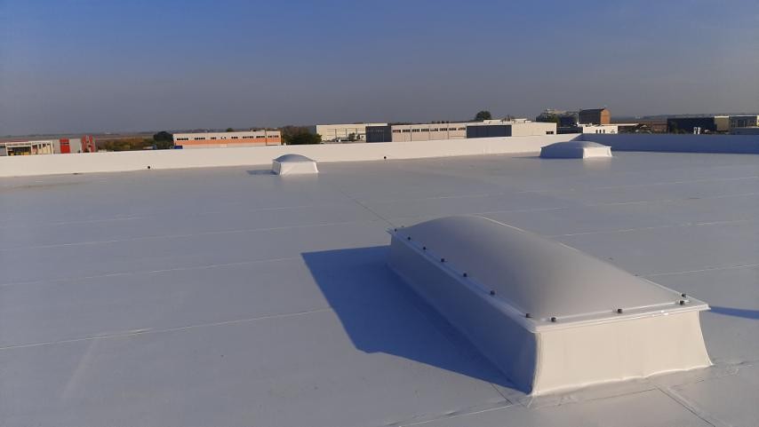
Roof domes / skylights / light strips may come in various sizes and shapes. Domes can have multiple functions, most commonly installed for natural lighting, smoke ventilation (fire safety), or air circulation within the building.
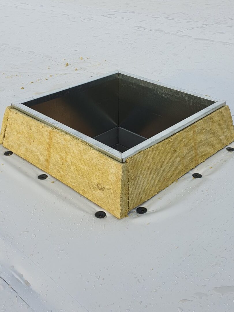
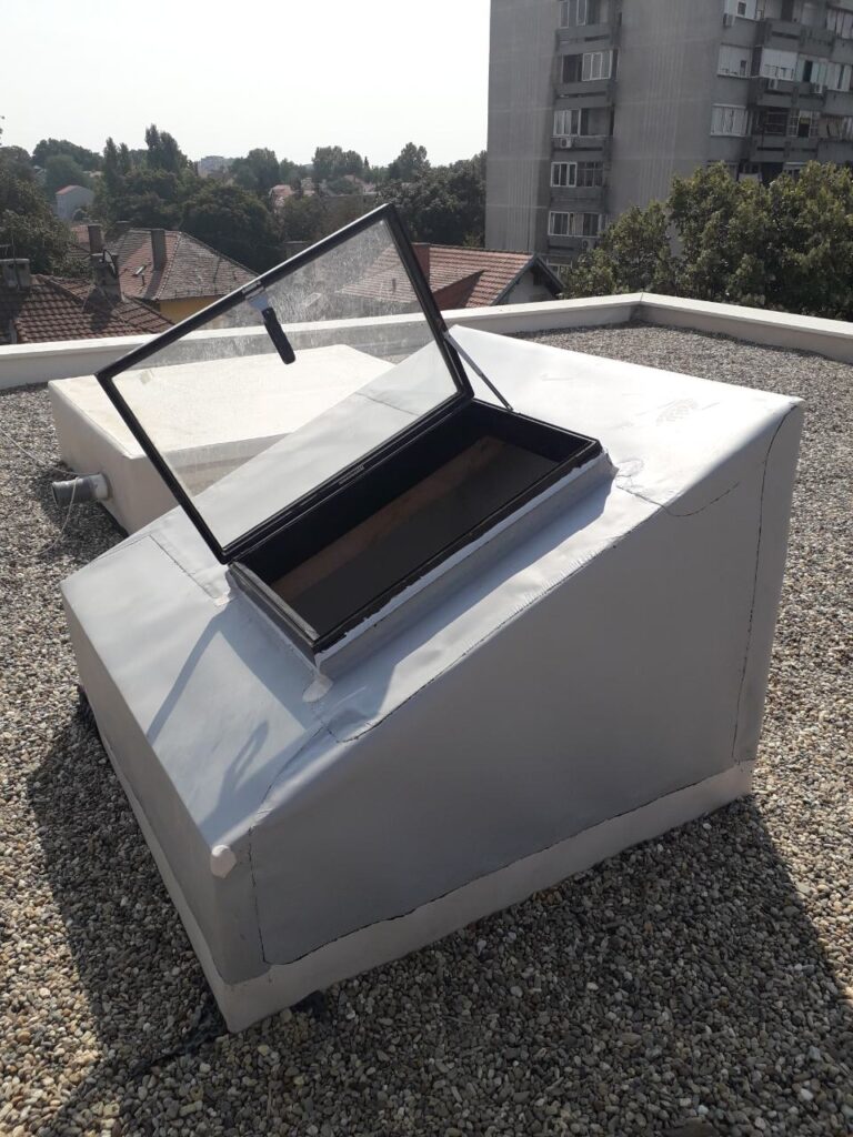
The detail shows two common types of roof domes. The first has a factory-made curb with integrated thermal insulation, while the second has a galvanized steel curb filled with mineral wool.
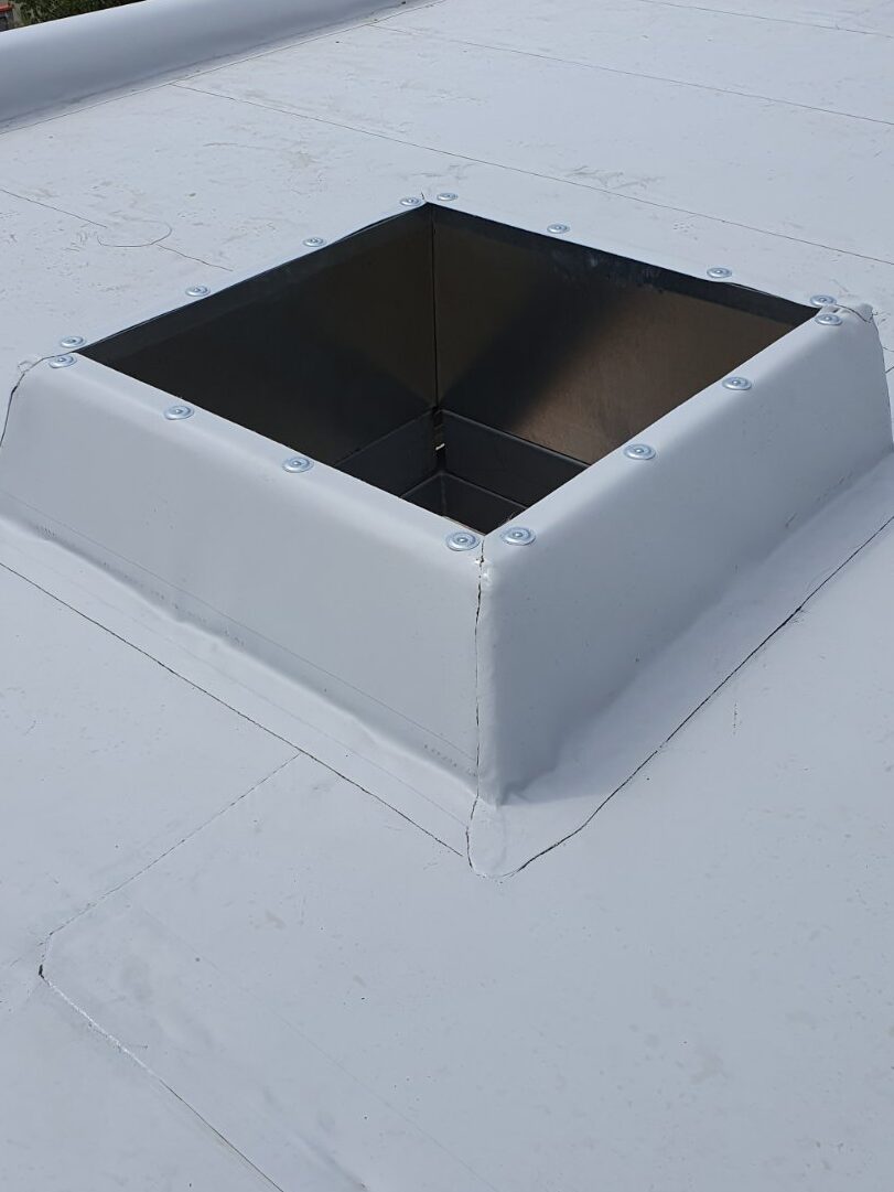
Installation of the waterproofing membrane around roof domes is usually coordinated with the dome manufacturer/installer.
It is important to note that roof domes require the installation of a steel substructure – a steel frame. Around this frame, a steel L-profile must be mounted to support the trapezoidal roof sheeting.
In practice, it often happens that no additional profile is installed around the dome’s steel substructure, causing deflection of the trapezoidal sheeting – which is a poor execution and requires correction prior to installing thermal and waterproofing layers.
Examples of roof curbs and domes:
DETAIL D5 – Waterproofing of Roof Bases for Large / Heavy HVAC Equipment
(For heavy fans and large metal ventilation ducts)
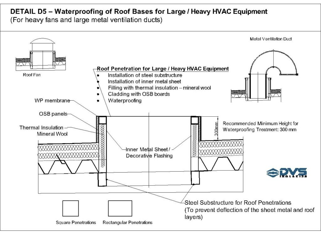
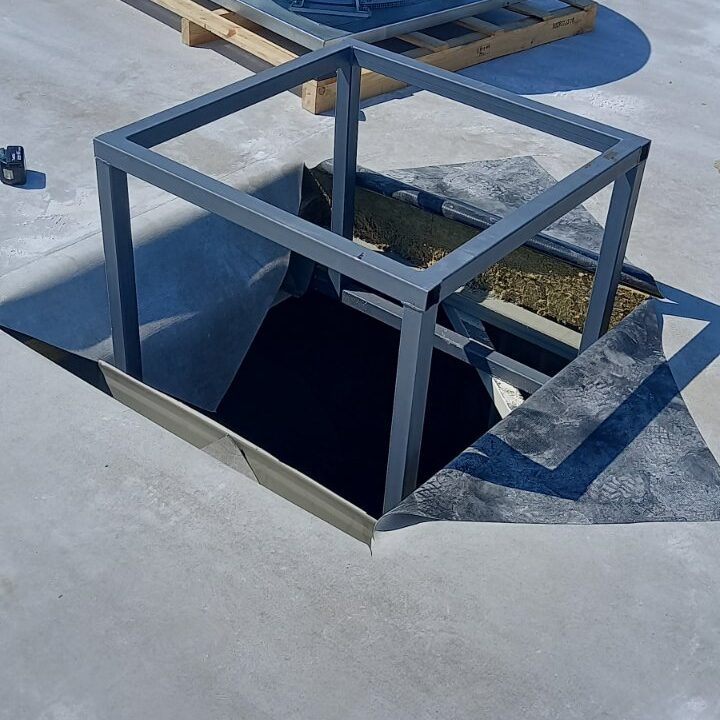
When cutting large roof openings, there is a risk of deflection of the roof covering, i.e., the load-bearing trapezoidal sheet.
To prevent excessive deflection of the layered roof, a steel substructure (steel frame) is installed prior to cutting, anchored to the roof structure.
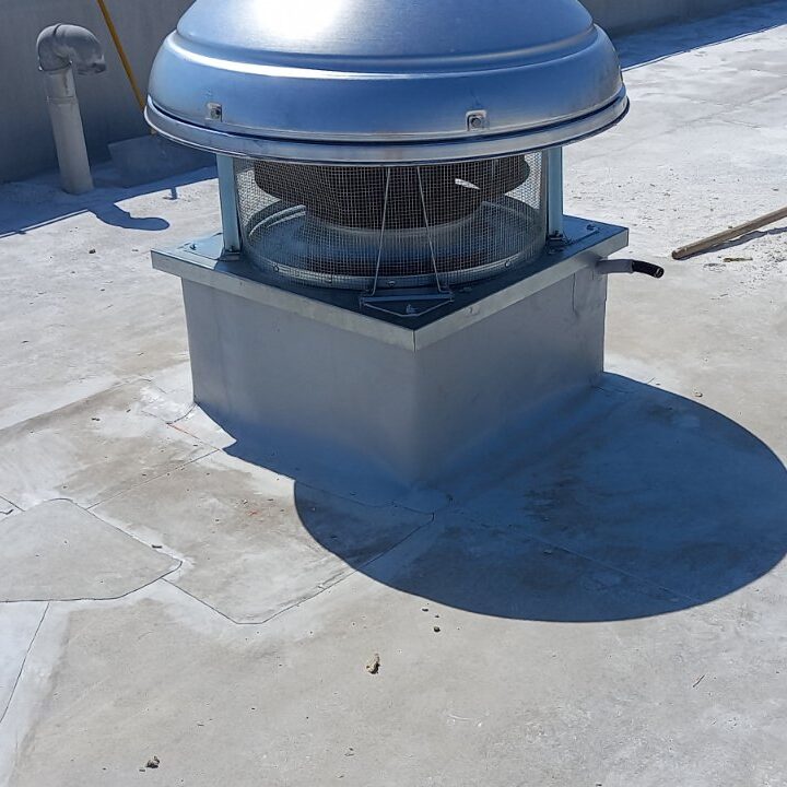
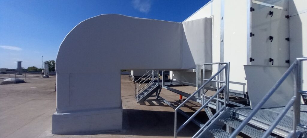
This method is also applied for mounting heavy equipment such as fans, air conditioning units, and similar.
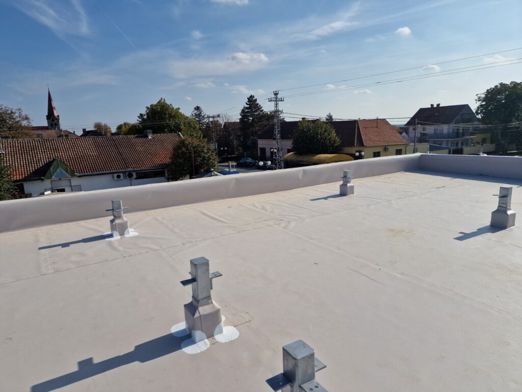
DETAIL D6 – Waterproofing of Steel Supports, Steel Columns, and Installation Pipes
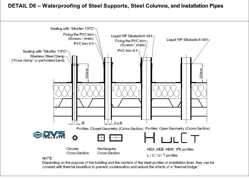
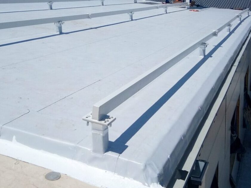
On flat roofs with layered systems, additional equipment often requires penetrations for steel installation pipes, steel posts, and steel supports.
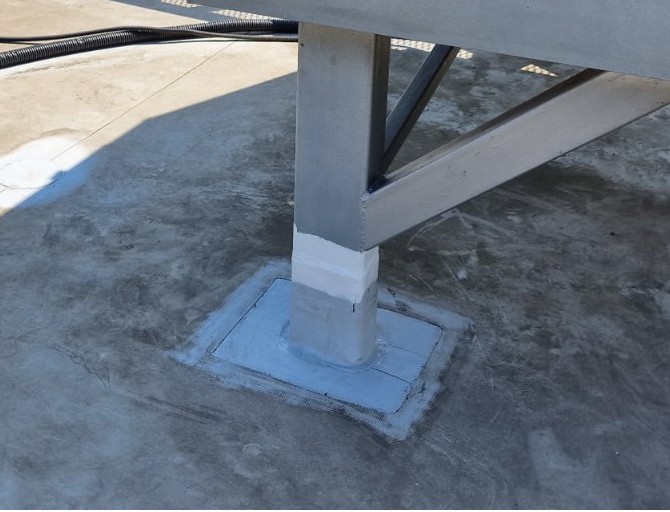
Waterproofing of steel profile penetrations is performed similarly to ventilation ducts.
Steel profiles may be of closed cross-section (circular, rectangular, or square) or open cross-section (HEA, HEB, HEM, L, C, T profiles, etc.).
For closed circular sections, waterproofing is completed by sealing and tightening with a stainless steel clamp / perforated band.
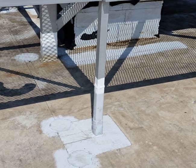
Rectangular and square profiles are waterproofed by installing a PVC/FPO termination bar, to which the membrane is welded. The junction between the bar and steel wall is sealed.
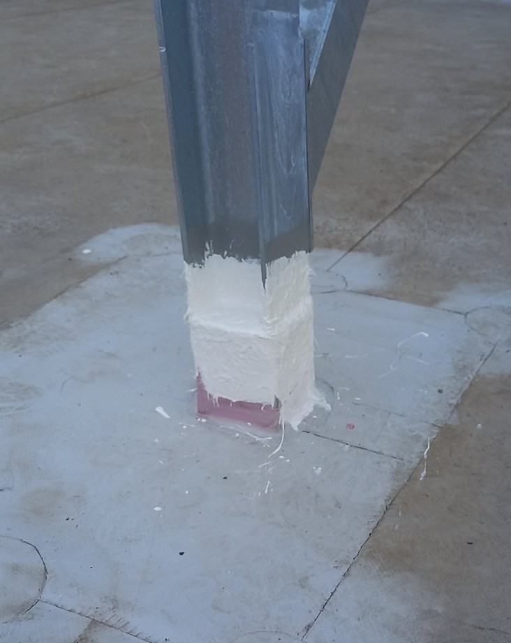
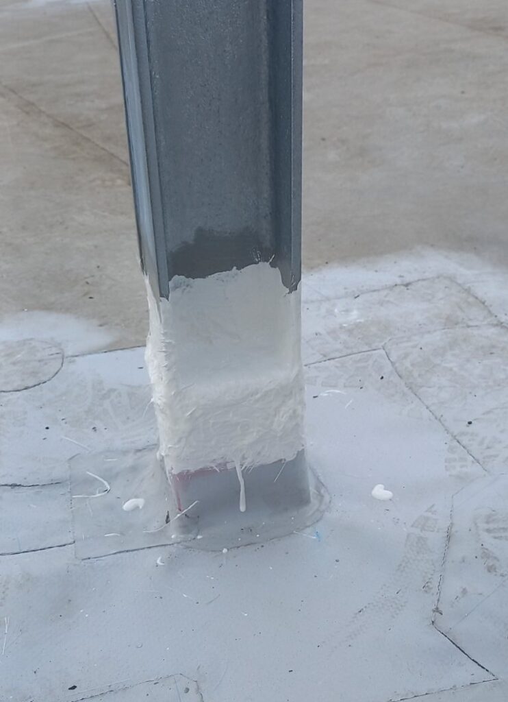
Profiles with open cross-sections are difficult to treat, so the junction between the waterproofing membrane and termination bar is additionally sealed with a liquid-applied membrane.
Liquid waterproofing membranes can also be used on closed profiles.
If condensation may occur due to a “thermal bridge,” a layer of thermal insulation is installed around the steel profiles.