- 25.02.2025.
- -
The execution of waterproofing works requires strict compliance with professional standards, manufacturers’ recommendations, as well as the application of practical solutions, proven details, and experience gained on construction sites.
With the development of new technologies and materials in the field of waterproofing, the execution of roof waterproofing systems is continuously being improved.
In addition to the above, there are standardized (typical) details that serve as guidelines for each project.
After these typical details are harmonized, execution details are defined for each individual building. These details are approved by the designer or supervising authority, with the consent of the investor’s representative.
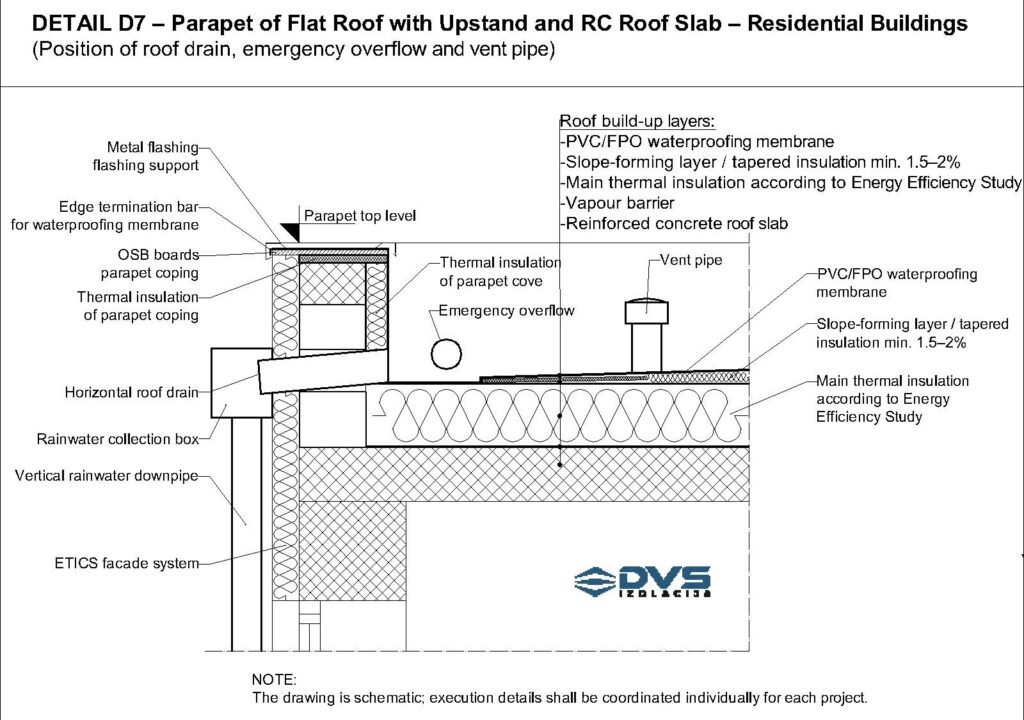
Parapet Wall Details – Flat Roof Upstand
(Detail D7, Detail D8)
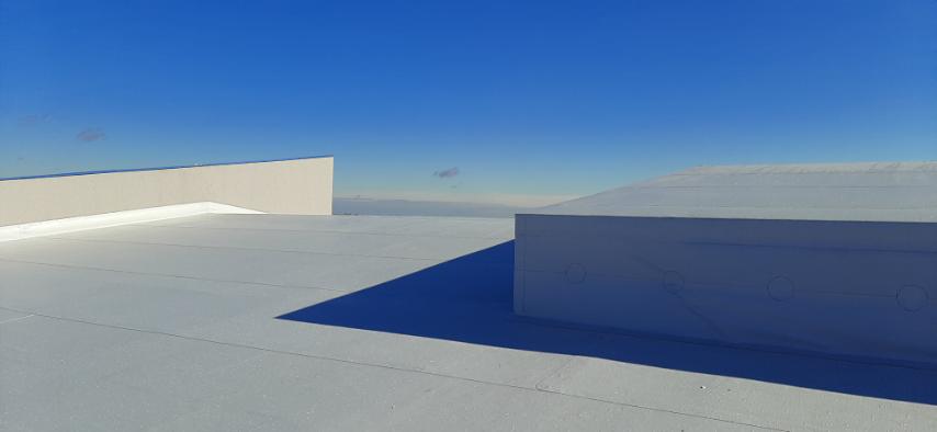
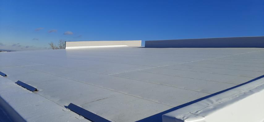
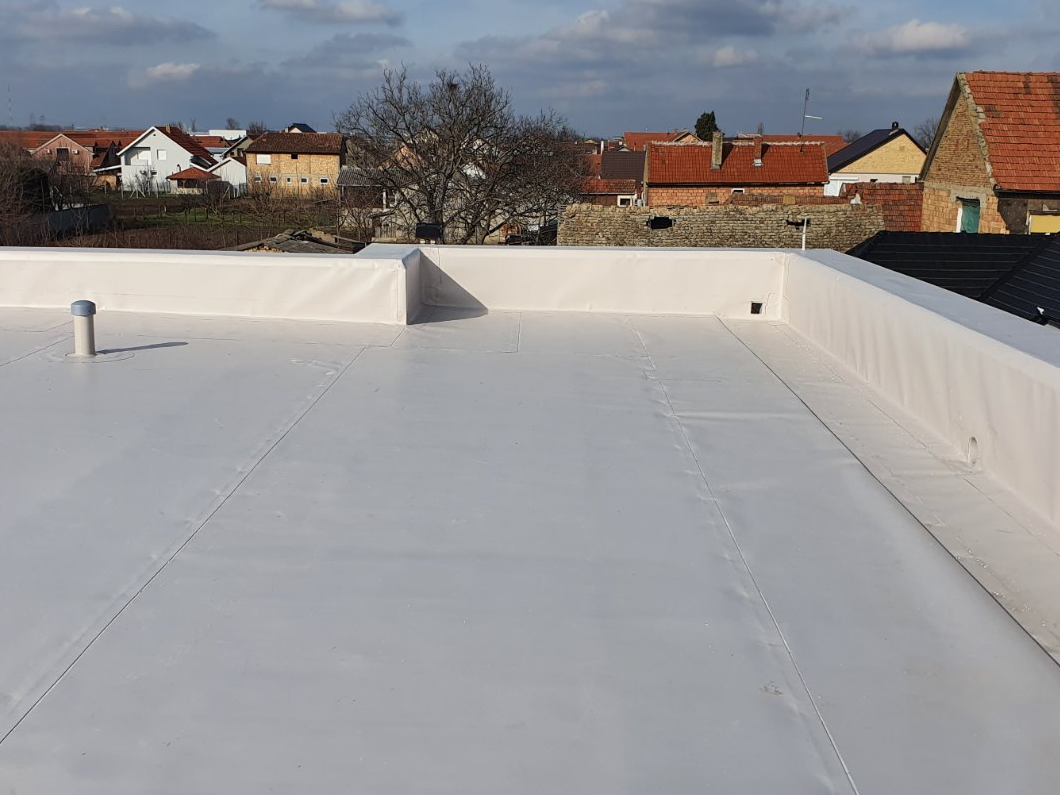
On flat roofs, a parapet wall (upstand) is most often constructed along the perimeter of the roof. This solution visually “conceals” the flat roof, achieving an aesthetically pleasing façade finish with a flat, horizontal top, thus contributing to the architectural integrity of the building.
In buildings where the roof or terrace reinforced concrete (RC) slab is monolithic, the waterproofing termination is most commonly executed in accordance with Detail D7. In this case, a parapet wall is formed on the roof slab and can be constructed from hollow clay blocks, Ytong blocks, or as a monolithic reinforced concrete parapet.
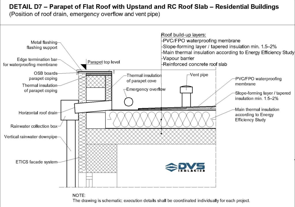
The waterproofing fully covers both the vertical and horizontal parts of the parapet, terminating at an edge profile clad with PVC/FPO material. This execution method ensures effective protection of both the roof surface and the parapet against water penetration into the interior space.
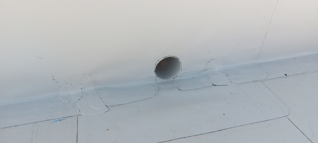
Horizontal gravity roof drain:
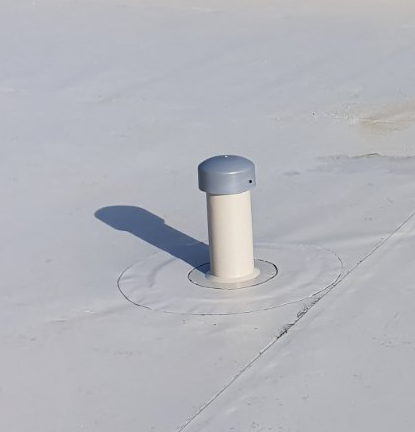
Vent pipe with cover:
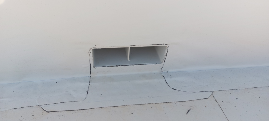
Emergency overflow – for large roof areas:
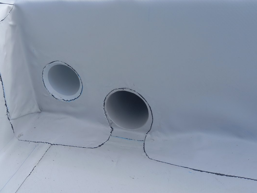
Horizontal gravity drain and emergency overflow – for smaller roof areas:
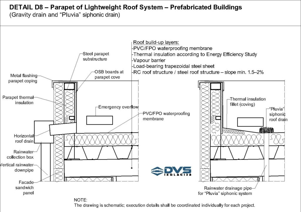
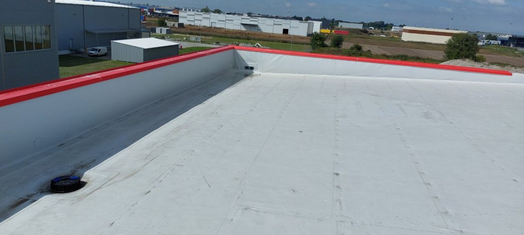
In prefabricated buildings, where Detail D8 is applied—most commonly in commercial facilities (office buildings, production plants, warehouses, shopping centers, etc.)—the waterproofing system also covers both the vertical and horizontal parts of the parapet, ensuring adequate water protection.
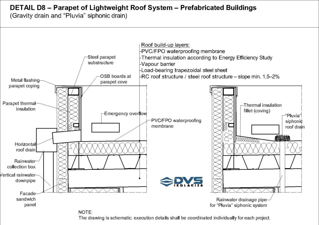
Depending on the rainwater drainage system, two standard solutions are used:
- Gravity drainage system, including external collection boxes and vertical downpipes.
- Siphonic drainage system (Pluvia system), where rainwater is drained internally through the building.
Vertical gravity roof drain:
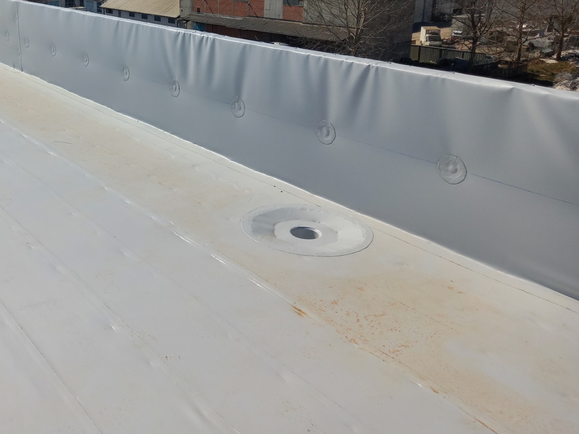
Siphonic drainage system – “Pluvia” roof drain:
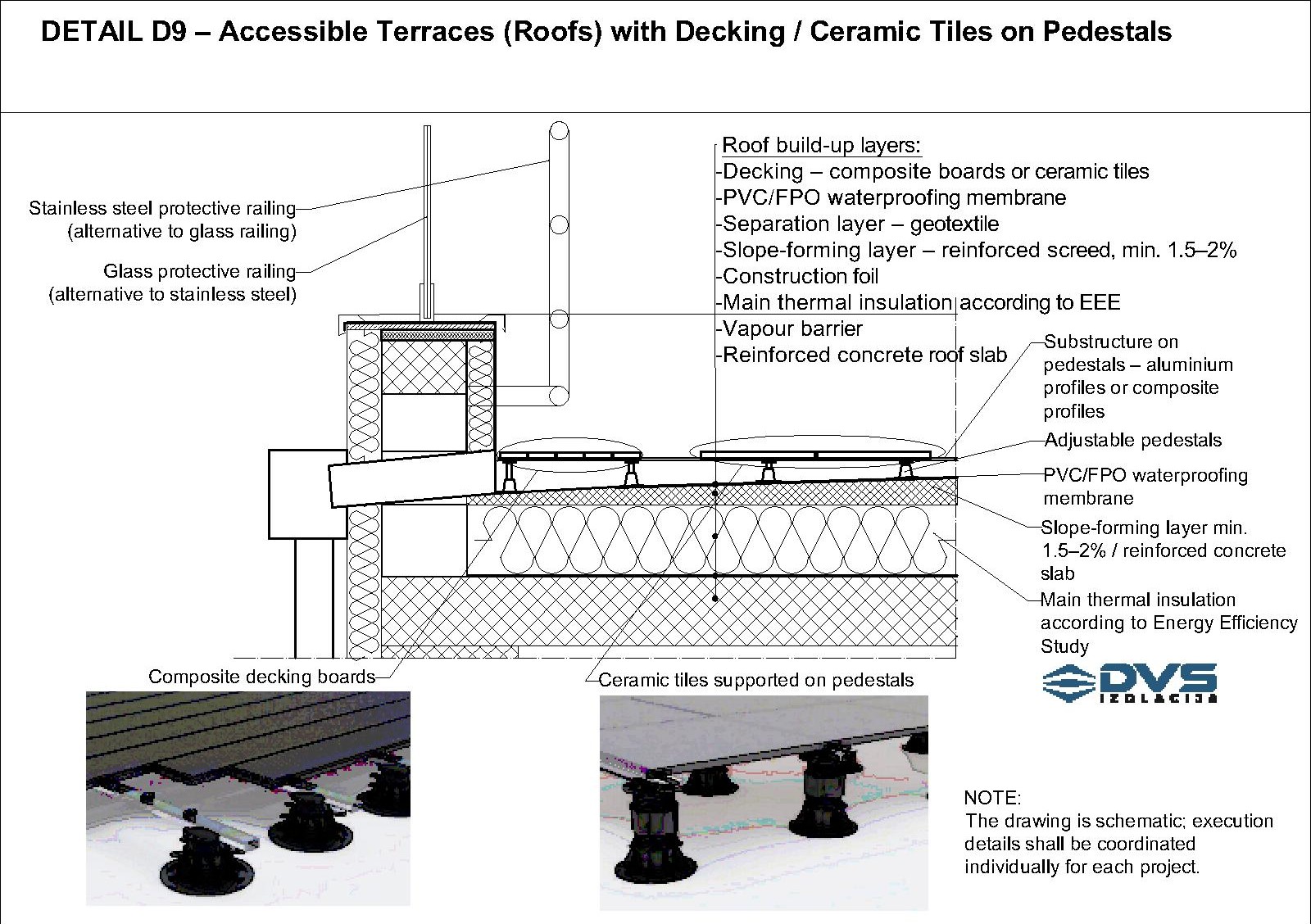
Walkable Roof Detail with Decking / Ceramic Tiles on Pedestals
(Detail D9)
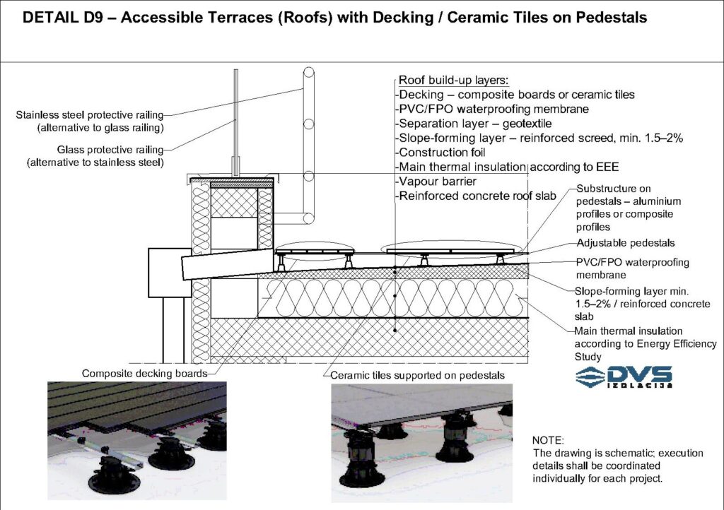
Walkable terraces and roofs are executed with appropriate protection of the waterproofing system to prevent damage.
Protection of waterproofing on walkable and load-bearing systems can be achieved in the following ways:
- Reinforced screed
- Reinforced screed with ceramic tiles
- Ballast layer of rounded gravel
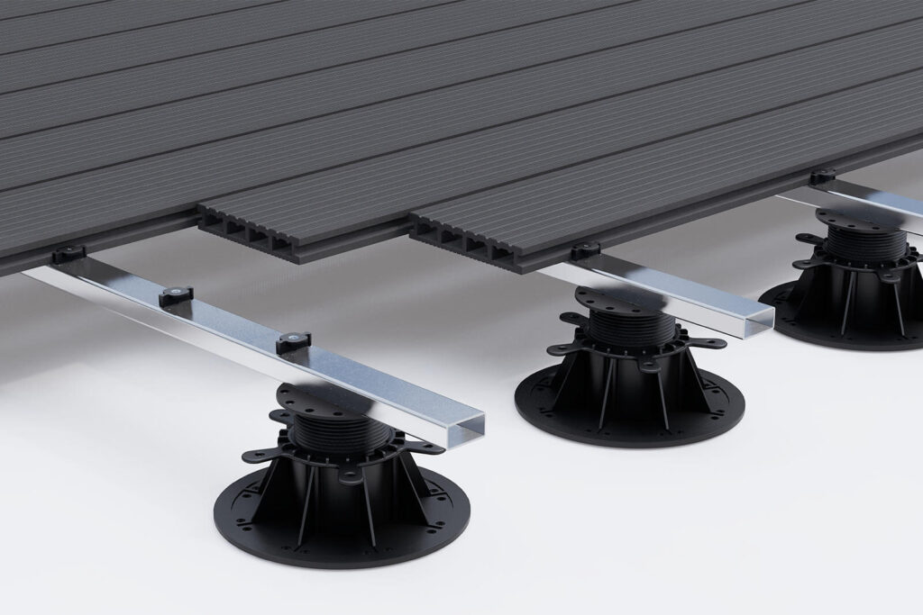
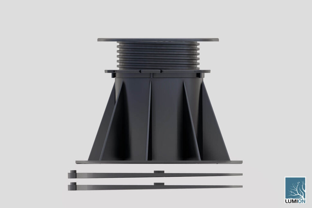
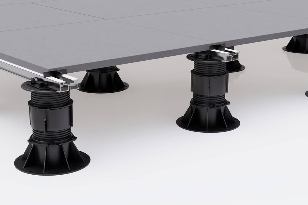
- Decking made of composite boards or ceramic tiles on adjustable pedestals
- Drainage layer with compost and vegetation (green roof)
The layers above the waterproofing have a dual function: they protect the membrane from mechanical damage and UV radiation, thereby extending its service life and increasing resistance to external influences.
Below are the typical layer configurations for walkable terraces with ceramic tiles and decking:
- Walkable terrace/roof layers with bonded ceramic tiles – waterproofing membrane
- Reinforced concrete slab
- Vapor barrier
- Main thermal insulation according to the Energy Efficiency Study (if residential space is below)
- Slope-forming layer with 1.5–2% inclination (reinforced screed or tapered insulation)
- Separation geotextile layer
- Waterproofing membrane for load-bearing systems
- Protective geotextile layer
- PE construction foil – slip layer (optional)
- Reinforced screed – waterproofing protection layer
- Polymer-cement waterproofing (protects the screed from moisture absorption and freezing)
- Tile adhesive
- Ceramic tiles
- Walkable terrace/roof layers with bonded ceramic tiles – liquid waterproofing membrane
- Reinforced concrete slab
- Vapor barrier
- Main thermal insulation according to the Energy Efficiency Study
- Slope-forming reinforced screed (1.5–2%)
- Liquid waterproofing with quartz sand broadcast (polyurethane liquid membrane)
- Tile adhesive
- Ceramic tiles
- Walkable terrace/roof layers with decking – waterproofing membrane
- Reinforced concrete slab
- Vapor barrier
- Main thermal insulation according to the Energy Efficiency Study
- Slope-forming reinforced screed
- Separation geotextile layer
- Waterproofing membrane for load-bearing systems
- Adjustable pedestals with pads
- Decking substructure (optional)
- Composite boards / ceramic tiles
- Walkable terrace/roof layers with decking – liquid waterproofing membrane
- Reinforced concrete slab
- Vapor barrier
- Main thermal insulation according to the Energy Efficiency Study
- Slope-forming reinforced screed (1.5–2%)
- Liquid waterproofing (polyurethane membrane)
- Adjustable pedestals with pads
- Decking substructure (optional)
- Composite boards / ceramic tiles
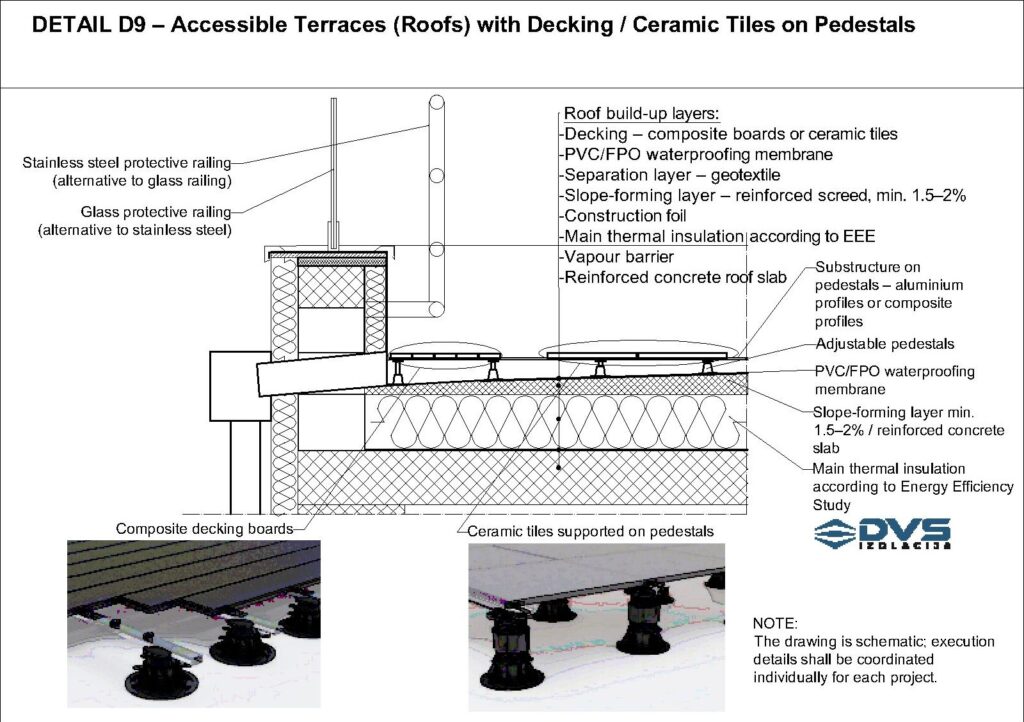
With the development of new finishing floor systems and composite materials, decking with composite boards or ceramic tiles on pedestals (Detail D9) is increasingly used.
Originally applied in hospitality facilities (restaurants, hotels, cafés), these systems have quickly found application in residential buildings as well.
Installing decking on flat roofs (terraces or roof areas) creates a walkable roof with numerous advantages:
- Protects the waterproofing membrane from damage, as no cast protective screed is required
- Allows easy dismantling of the decking for inspection of the waterproofing system
In systems with bonded ceramic tiles and screed, inspection of the waterproofing requires complete removal of existing layers, including:
- Removal of ceramic tiles
- Demolition and removal of the screed
- After waterproofing repair, reinstallation of geotextile, casting a new screed, and installation of new ceramic tiles.
Although bonded ceramic tile systems provide greater stability and load capacity, they require significantly higher investment in case of waterproofing damage and leak repair.
Conversely, decking systems avoid mechanical damage caused by screed installation, reducing maintenance and operating costs and making them a more cost-effective long-term solution for investors.
Financial investments in bonded ceramic tile systems (layer options 1 and 2) are practically equivalent to decking systems (layer options 3 and 4).
Depending on the design solution and intended use of the terrace/roof, the optimal system is selected for each project to achieve the best balance between investment costs and long-term functionality.
Detail D9 illustrates the system solution for installing decking on a terrace/roof with a waterproofing membrane (layer options 3 and 4).
Decking with composite boards:
Adjustable pedestals with substructure:
Ceramic tiles on pedestals:
(Photos sourced from dekigzona.com)
Wall Waterproofing Detail – Cove (Fillet)
(Detail D10)
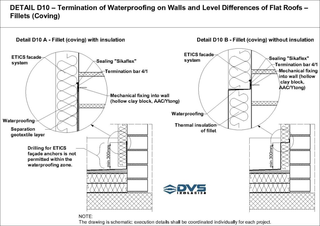
Termination of waterproofing at roof level changes, wall junctions, or parapets can be executed in several ways.
The most commonly used solution is termination at a 4/1 edge profile, clad with PVC or FPO material.
According to manufacturers’ recommendations, the cove must have a minimum height of 30 cm (300 mm) to ensure optimal protection against water penetration.
Installation sequence of coves and edge profiles:
- Fixing the edge profile to the wall using screws/anchors (RC walls, hollow blocks, Ytong, prefabricated walls, etc.)
- Installation of thermal insulation or separation geotextile layer
- Hot-air welding of the waterproofing membrane to the edge profile
- Sealing joints between the edge profile and wall with polyurethane sealant
For walkable terraces/roofs (Detail D10 A), the cove may be executed without thermal insulation and positioned behind the façade cladding, effectively preventing damage to the waterproofing membrane during use.
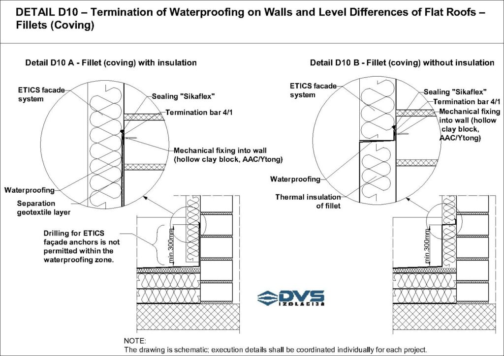
No drilling for façade anchors is allowed in the overlap zone between the cove and façade cladding. The dimensions and position of this zone are defined individually for each project.
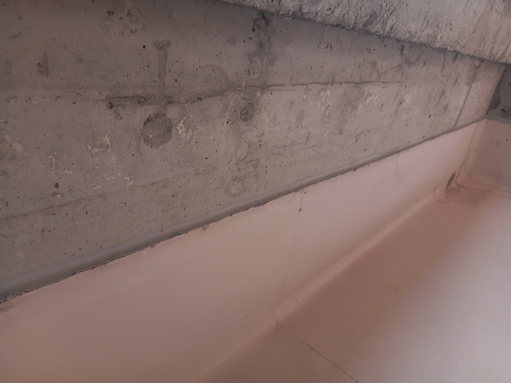
Cove on RC wall / parapet:
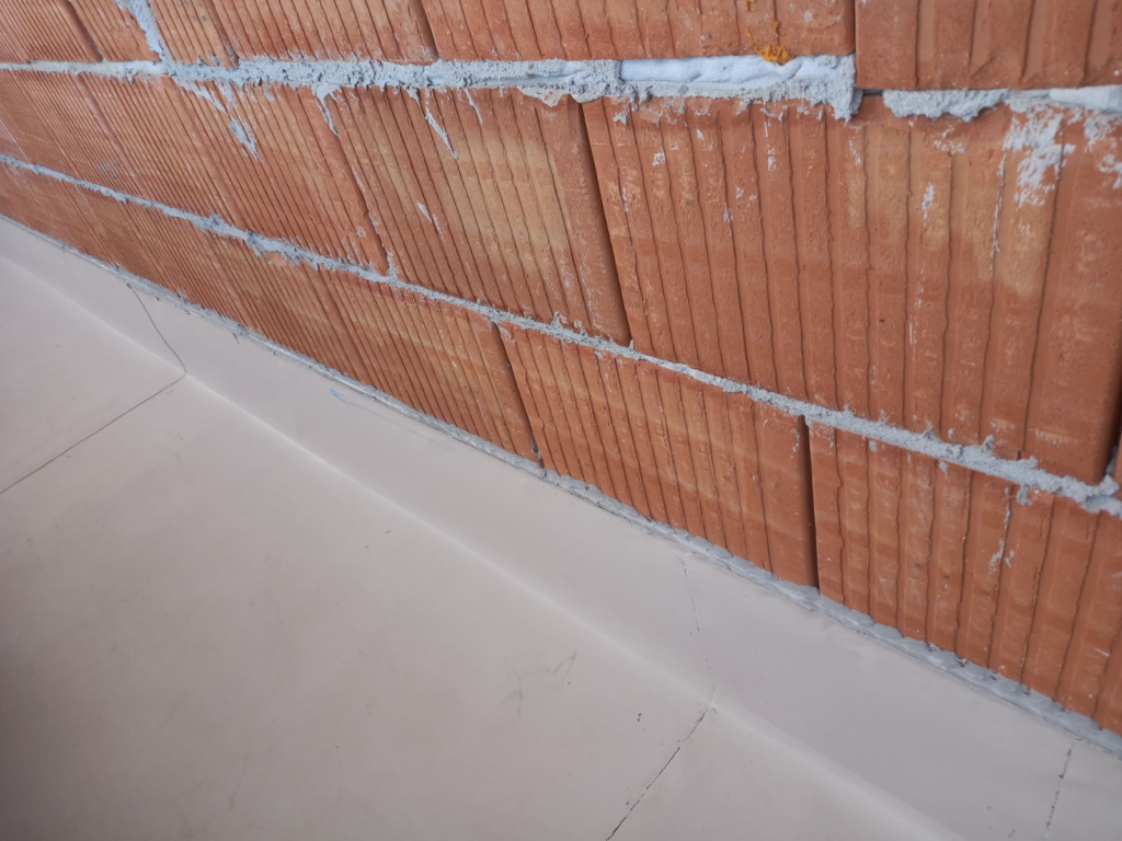
Cove on hollow block wall:
For non-walkable terraces/roofs (Detail D10 B), the cove is insulated with thermal insulation, over which the waterproofing membrane is installed and welded to the edge profile. The insulation thickness is determined according to the Energy Efficiency Study and façade system type.
In both cases, the edge profile is positioned beneath the façade cladding, eliminating the risk of water penetration due to precipitation and ensuring long-term system protection.
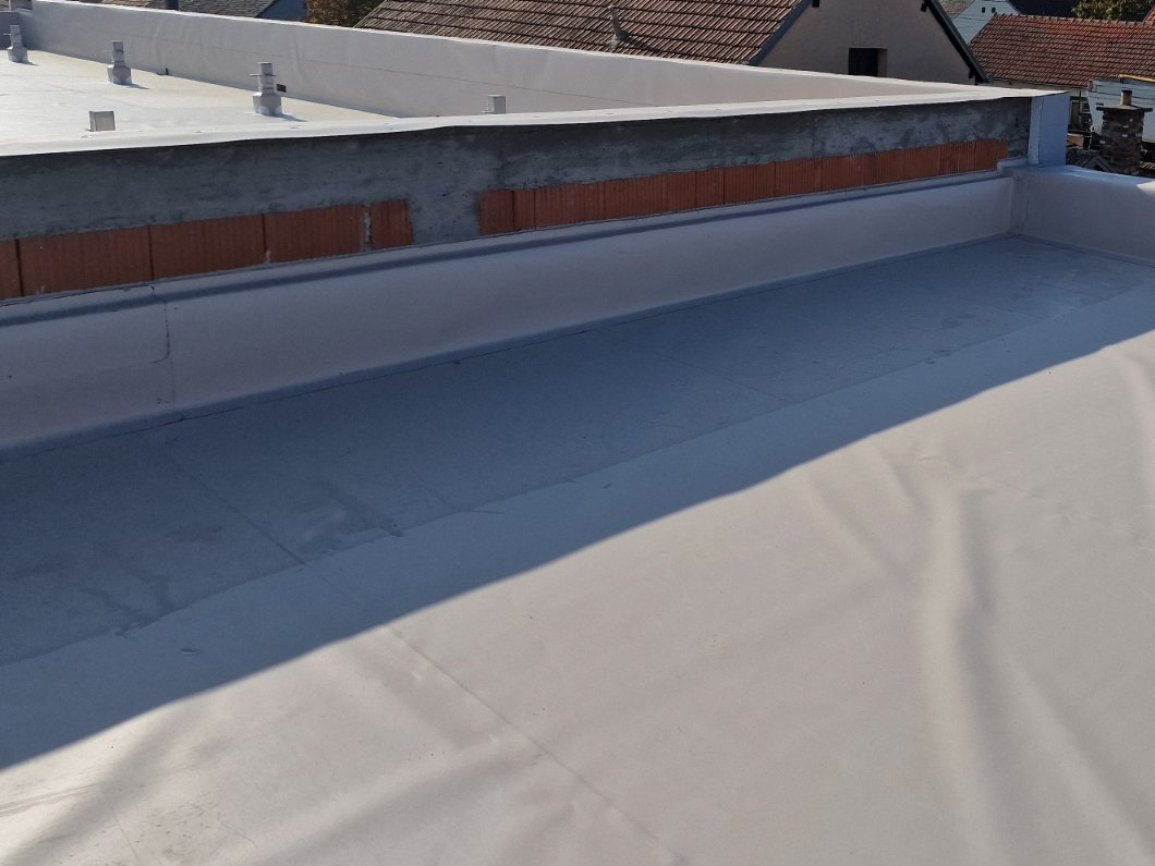
Fillet (coving) with thermal insulation on hollow clay block wall
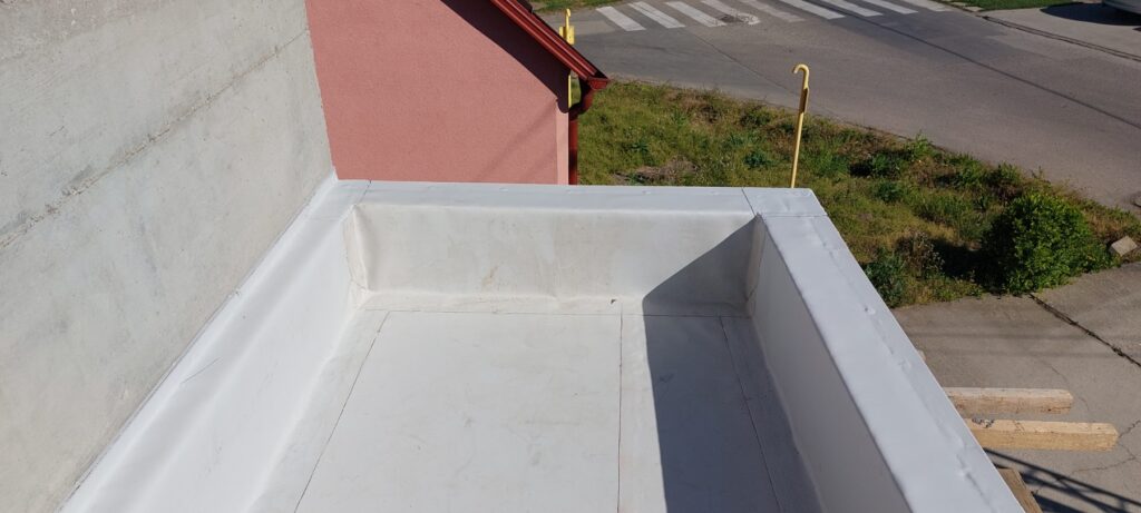
Fillet (coving) on reinforced concrete wall / parapet / “concrete canvas”
Waterproofing Detail at Flat Roof Level Differences in Prefabricated Buildings
(Detail D11)
In prefabricated buildings, it is common to have structures with different roof heights connected into a single unit.
Typically, the administrative section (offices, cafeteria, changing rooms, boiler room, etc.) is lower, while the main facility (production hall, warehouse, shopping center, etc.) is higher.
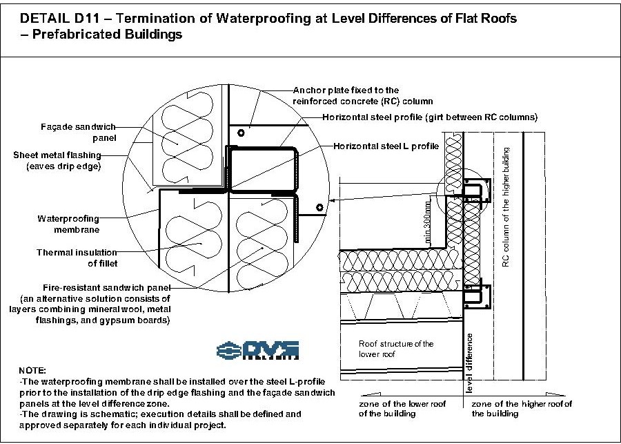
At the junction of these structures, a roof level difference occurs, where façade panels of the higher building extend above the lower roof.
If the façade system is ventilated or ETICS, waterproofing termination is executed using cove details (Detail D10).
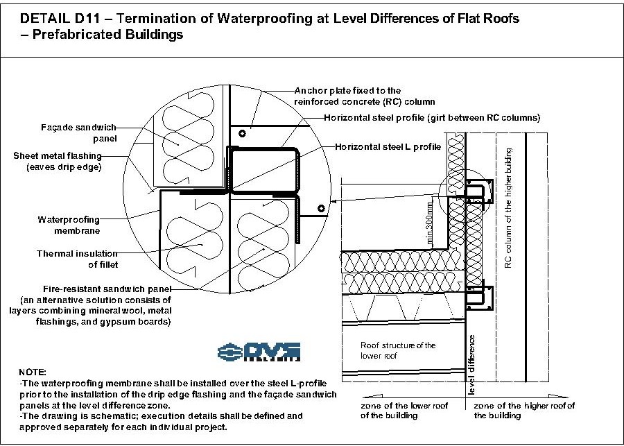
To ensure proper and durable waterproofing at this junction, practice has shown the necessity of interrupting the façade of the higher building, allowing the waterproofing membrane to be installed and turned up behind the façade panels.
Detail D11 shows waterproofing installation on a steel L-profile prior to mounting the drip edge and façade panels.
This solution prevents water penetration at flashings, horizontal façade panel joints, vertical flashings (“omega” profiles), and concealed vertical panel joints.
This detail is coordinated with designers, supervision, and investor representatives for each project to ensure long-term protection.
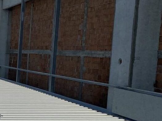
Example of roof level difference solution with steel substructure:
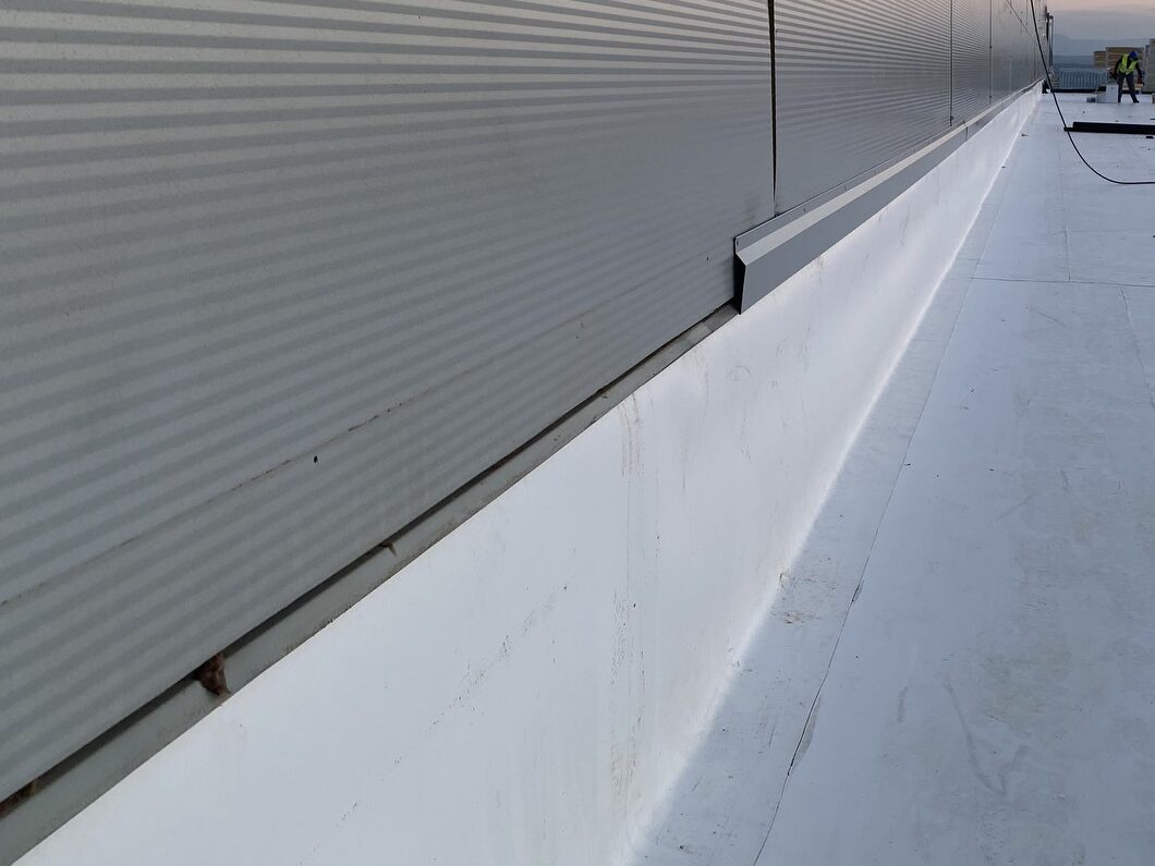
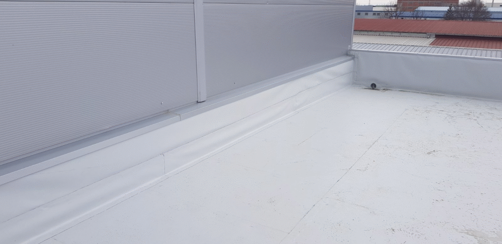
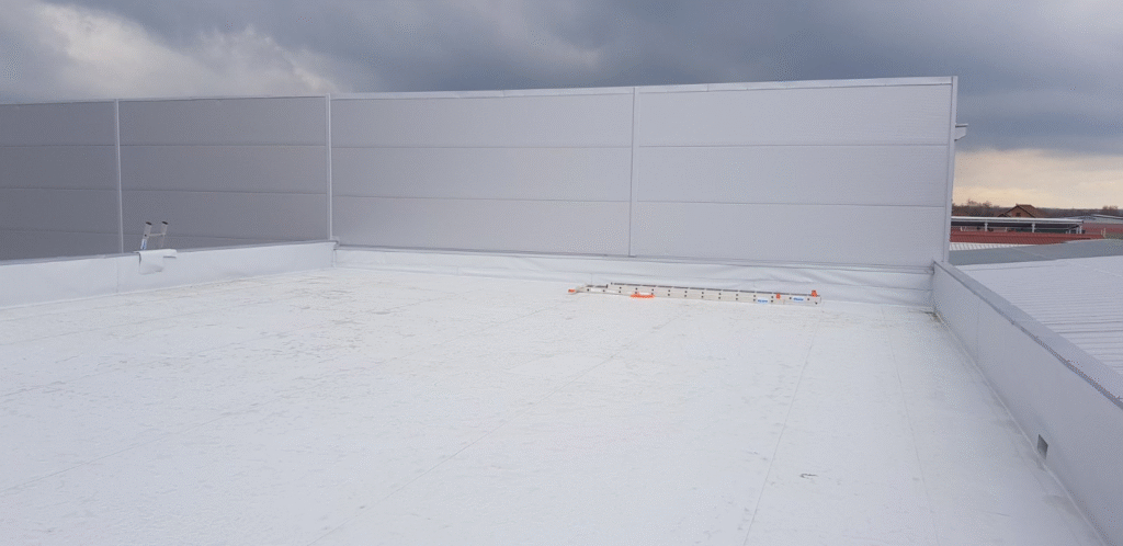
Appearance after installation of insulation, waterproofing, and façade panels:
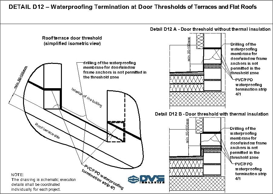
Waterproofing Detail at Terrace/Roof Door Thresholds
(Detail D12)
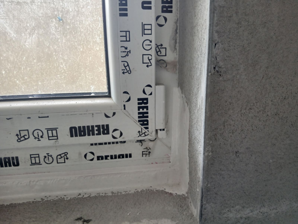
The junction between waterproofing and façade joinery is often a weak point, especially if execution details are not coordinated in time.
If proper waterproofing of thresholds is overlooked during construction, water penetration into interior spaces may occur during use.
Repairing such defects requires significant investment and complex interventions, including dismantling of joinery and removal of terrace layers.
For terrace/roof doors and low windows, waterproofing must fully cover the door threshold or window sill.
This execution ensures complete waterproofing of the threshold area and prevents water from passing beneath façade joinery.
Any water appearing beneath the joinery (due to condensation, rainwater runoff, etc.) is safely directed outward by the waterproofing system.
Thresholds can be executed without thermal insulation (Detail D12 A) or with thermal insulation (Detail D12 B).
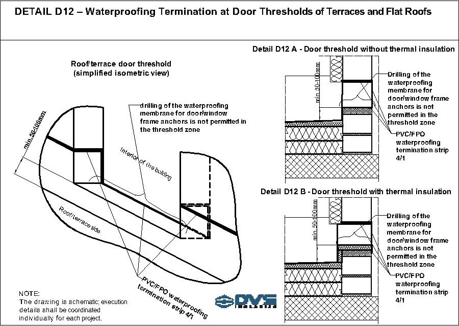
It is important to note that drilling is not permitted in the lower horizontal waterproofing zone of thresholds in order to preserve membrane integrity.
Schematic door threshold detail:
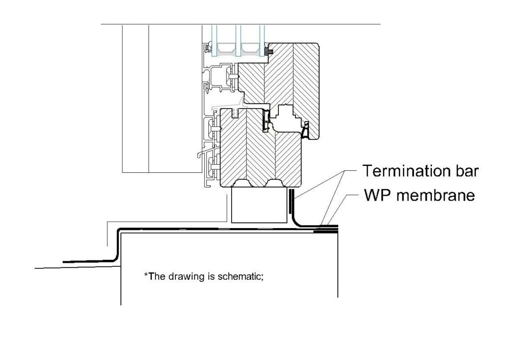
This detail is coordinated individually for each project with designers, supervision, and investor representatives to ensure proper waterproofing and long-term protection.
Door threshold waterproofing before joinery installation:
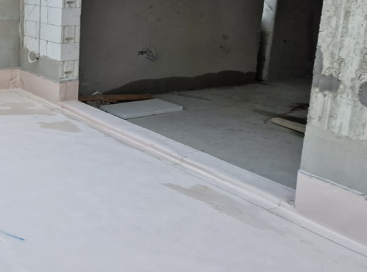
Internal-side joinery waterproofing (Sikalastic 614 / Sikalastic 641):
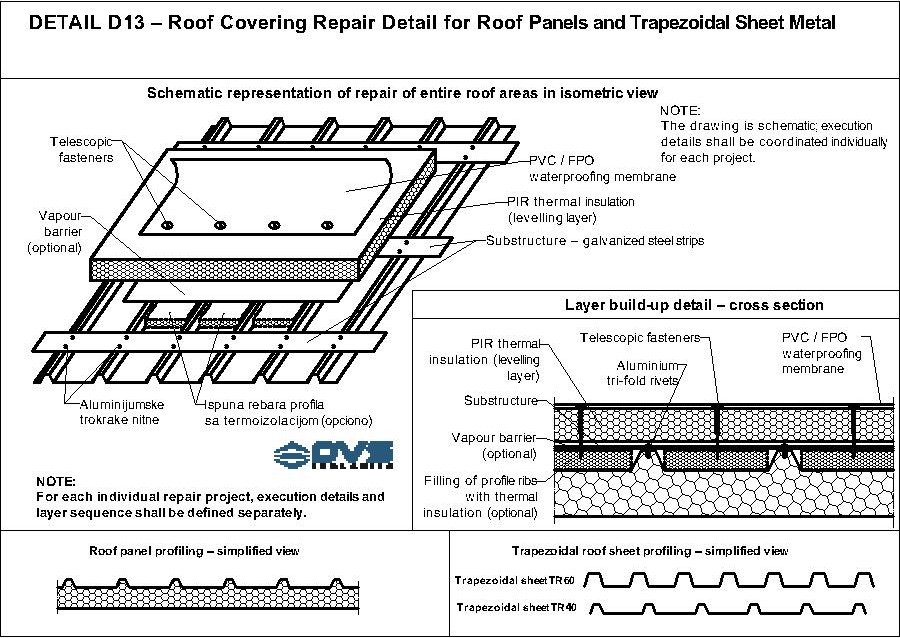
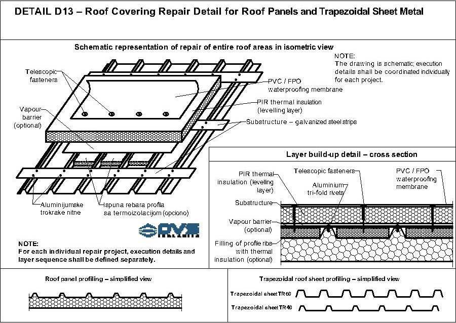
Roof Cover Rehabilitation – Sandwich Panels and Trapezoidal Sheets
(Detail D13)
In practice, there is an increasing need for complete rehabilitation of existing roof surfaces.
Problems with water penetration on roofs made of sandwich panels or trapezoidal steel sheets are common.
A detailed assessment of the existing roof condition is required, sometimes including pull-off tests of telescopic fasteners to determine substrate load-bearing capacity.
If the sheet thickness is less than 0.75 mm, galvanized or plastic-coated steel strips with thickness > 0.75 mm and width 100 mm are installed to ensure adequate pull-out resistance.
The substructure strips are fixed at the crest of the profiles using aluminum tri-fold rivets, which expand during installation and provide the required load-bearing capacity.
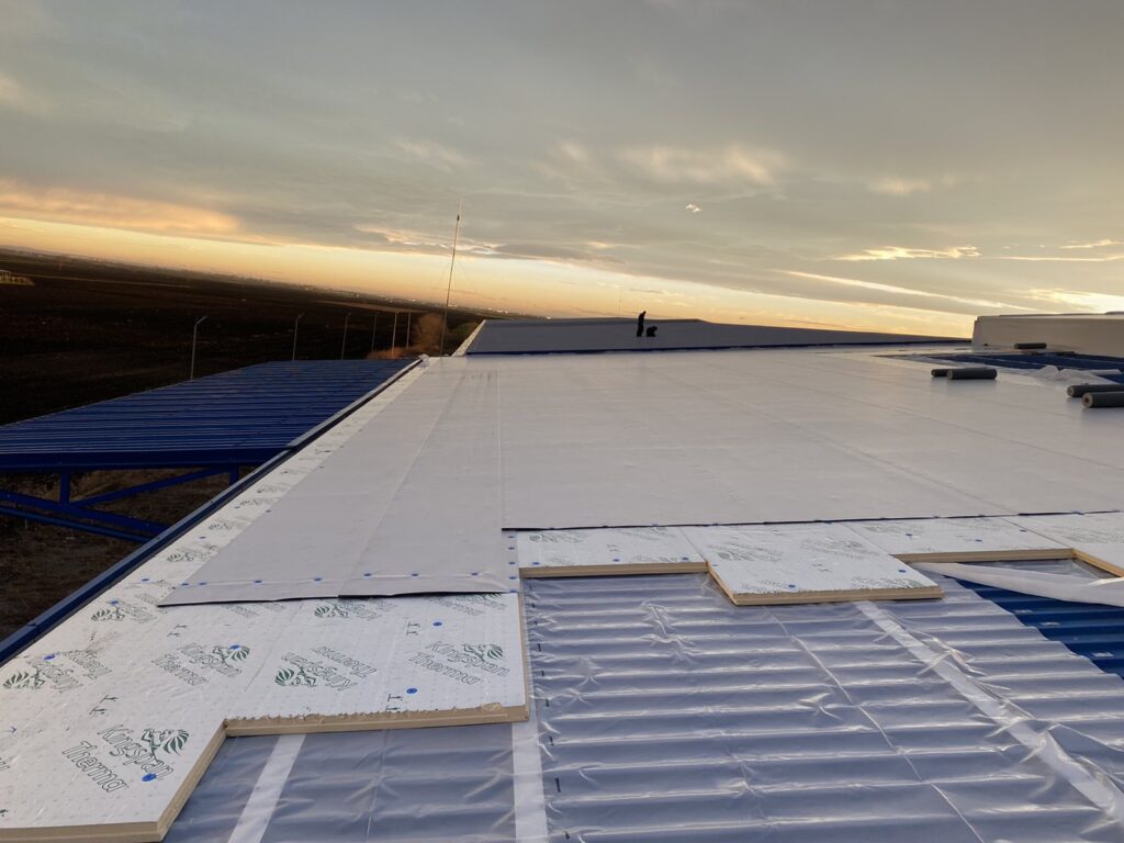
To enable waterproofing installation, a leveling layer is required. PIR thermal insulation is commonly used to fill profile ribs and create a leveling surface.
After PIR insulation installation, a PVC/FPO waterproofing membrane is installed and mechanically fixed with telescopic fasteners according to wind load calculations.
This rehabilitation method has proven to be an efficient solution for investors, providing excellent thermal and waterproofing performance with relatively low investment. A major benefit is that normal activities inside the building can continue uninterrupted during roof rehabilitation works.
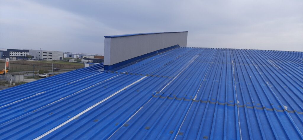
Roof before rehabilitation:
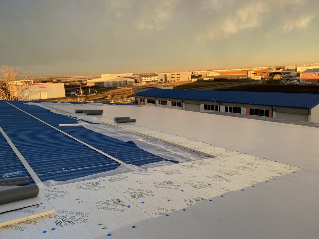
Roof during rehabilitation:
Roof after rehabilitation: